


Groundsmaster 4100--D Page 6 -- 5 Axles, Planetaries and Brakes
3. Chock rear wheels and jack up front of machine (see
Jacking Instructions in Chapter 1 -- Safety). Support ma-
chine with suitable jack stands.
4. Remove front wheel assembly.
5. Remove hydraulic wheel motor (see Front Wheel
Motors in Service and Repairs section of Chapter 4 --
Hydraulic System).
6. Disconnect brake cable from pull rod on brake as-
sembly.
7. Support brake assembly to prevent it from falling.
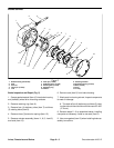
8. Remove four (4) flange head screws (item 9) secur-
ing brake assembly to machine. Remove brake assem-
bly taking care to not drop splined brake coupler as
brake assembly is removed.
9. Remove splined brake coupler.
10.Complete brake inspection and repair (see Brake In-
spection and Repair in this section).
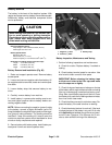
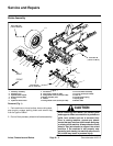
Installation (Fig. 1)
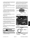
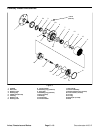
1. Slide splined brake coupler into brake assembly.
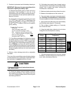
NOTE:The steppedendofthe coupler must be installed
toward the hydraulic wheel motor (Fig. 2).
2. Position brake assembly to frame, aligning splined
brake coupler with input shaft on planetary wheel drive.
3. Install four (4) flange head screws to secure brake
assembly to frame. Torque screws in a crossing pattern
from 75 to 85 ft--lb (101 to 115 N--m).
4. Install brake cable to pull rod on brake assembly.
Brake cable end should be completely threaded onto
pull rod.
5. Install new O--ring on hydraulic wheel motor. Install
wheel motor and torque cap screws from 75 to 85 ft-- lb
(101 to 115 N--m).
6. Install wheel assembly.
WARNING
Failure to maintain proper torque could result in
failure or loss ofwheeland may result inperson-
al injury.
7. Lower machine to ground. Torque lug nuts from 85
to 100 ft--lb (115 to 135 N--m).
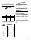
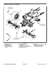
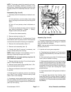
8. Make sure drain plug is installed in bottom of brake
assembly (Fig. 3). Fill planetary wheel drive/brake as-
sembly with SAE 85W--140 gear lube. Capacity is
approximately 16 fl. oz. (0.47 liters) per wheel.
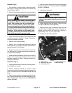
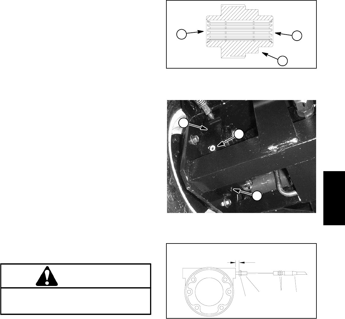
9. Check and adjust brake cables for proper brake op-
eration. If necessary, adjust brake cable jam nuts at
frame bracket so that pull rod jam nut is positioned from
0.470” to 0.530” (12.0 to 13.4 mm) from brake casting
surface when brakes are disengaged (Fig. 4).
1. Brake coupler step
2. Hydraulic motor end
3. Planetary assembly end
Figure 2
1
2
3
1. Brake housing
2. Check plug
3. Drain plug
Figure 3
1
2
3
1. Pull rod jam nut
2. Brake cable end
3. Cable jam nut
4. Brake cable
Figure 4
1
2
3
4
0.470” to 0.530”
(12.0 to 13.4 mm)
Axles, Planetaries
and Brakes