


Groundsmaster 4100--DPage 5 -- 10Electrical System
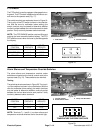
Cutting Deck Raise and Lower Switches
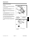
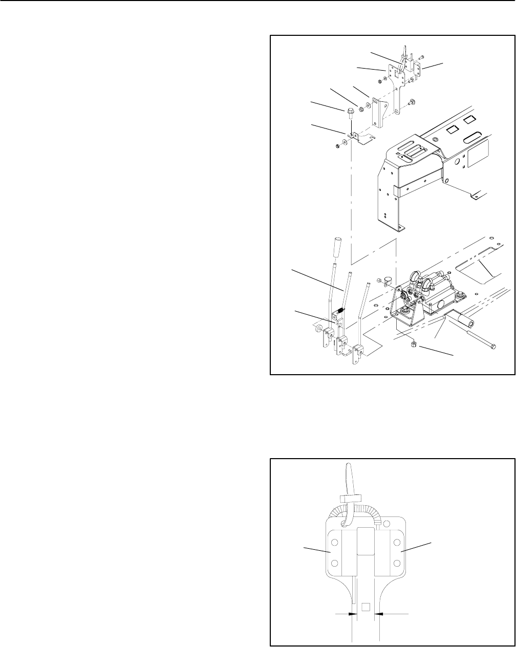
Adjustment (Fig. 9)
1. Park machine on a level surface, lower cutting deck,
stop engine, engage parking brake and remove key
from the ignition switch. Remove console housing.
2. Thecuttingdeckraiseandlower switchescan bead-
justed for correct operation by repositioning the
switch(es).
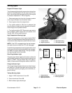
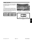
A. The distance between switches should be from
0.595” to 0.655” (15.2 to 16.6 mm) (Fig. 10).
B. The lever bracket (item 4) should be parallel with
the center deck lift/lower lever. If lever bracket ad-
justment is needed, loosen flange bolts (item 6) and
reposition lever bracket.
C. Switch surfaces need to be parallel to each other
and also to the switch actuator on center lift/lower le-
ver (item 9).Ifnecessary, switch plate (item 3) can be
rotated after loosening flange nut (item 5).
3. After any switch adjustment, unplug switch connec-
tor from machine harness and check for correct switch
operation using a multimeter:
A. The raise switch should be closed (continuity)
when the center deck lift/lower lever is in the neutral
position. As the lift/lower lever is slowly pulled back,
the raise switch should open (no continuity) after the
lever has removed all free play (with no spool move-
ment in lift/lower control valve) but before the deck is
lifted.
B. The lower switch should be open (no continuity)
when the center deck lift/lower lever is in the neutral
position. As the lift/lower lever is slowly pushed for-
ward, the lower switch should close (continuity) be-
fore the lever reaches full forward travel.
4. If switch operation is too sensitive, increasedistance
between switches by repositioning one or both
switches.Ifswitch operation is notsensitive enough, de-
crease distance between switches by repositioning one
or both switches. Recheck operation of switches after
repositioning.
5. If switches cannot be adjusted for correct operation,
exchange position of switches. Recheck operation of
switches.
NOTE: If correct switch operation cannot be achieved,
replace one or both switches. Recheck switchoperation
after replacement.
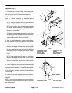
1. Deck lower switch
2. Deck raise switch
3. Switch plate
4. Lever bracket
5. Flange nut
6. Flange bolt (2 used)
7. Tab plate
8. Deck lift/lower lever
9. Switch actuator
10. Lock nut (2 used)
Figure 9
9
2
4
3
1
8
7
6
5
10
1. Deck lower switch 2. Deck raise switch
Figure 10
2
1
0.595” to 0.655”
(15.2 to 16.6 mm)