


Groundsmaster 4100--D Page 5 -- 31 Electrical System
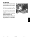
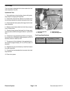
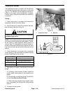
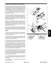
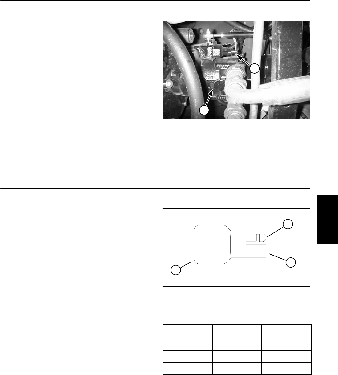
Traction Neutral Switch
The traction neutral switch is closed when the traction
pedalisin theneutralpositionandopens whenthepedal
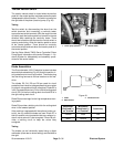
is depressed in either direction. The switch is located on
the right side of the piston (traction) pump (Fig. 48).
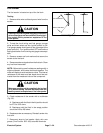
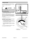
Testing
Test the switch by disconnecting the wires from the
switch terminals and connecting a continuity tester
across the two switch terminals. With the engine turned
off,slowly pushthetraction pedal in a forward or reverse
direction while watching the continuity tester. There
should be indications that the traction neutral switch is
opening and closing. Allow the traction pedal to return
to the neutral position. There should be continuity
across the switch terminals when the traction pedal is in
the neutral position.
See the Eaton Model 72400 Servo Controlled Piston
Pump Repair Information at the end of Chapter 4 -- Hy-
draulic System for disassembly and assembly proce-
dures for the neutral switch.
1. Piston pump (bottom) 2. Neutral switch
Figure 48
1
2
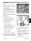
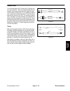
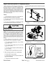
Diode Assemblies
The Groundsmaster 4100--D electrical system includes
several diode assemblies (Fig. 49) that are used for cir-
cuit protection and circuit logic control. The diodes plug
into the wiring harness at various locations on the ma-
chine.
The diodes D2, D4, D5 and D6 are used for circuit
protectionfrom inductivevoltagespikes thatoccur when
a hydraulic valve solenoid is de--energized. Diode D2 is
in the Transport/Mow circuit,D4 isin the left cutting deck
circuit, D5 is in the front cutting deck circuit and D6 is in
the right cutting deck circuit.
Diode D9 provides logic for the high temperature warn-
ing system.
Diode D3 provides a latching circuit for the cutting deck
when in the lowered position.
If the machine is equipped with the optional cruise con-
trol kit, two (2) additional diodes are used. Diode D7 in
this kit is used for circuit protection that occur when a hy-
draulic valve solenoid is de--energized. Diode D8 pro-
vides a latching circuit to keep the cruise relay
energized.
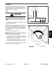
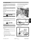
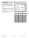
Testing
The diodes can be individually tested using a digital
multimeter (diode test or ohms setting) and the table to
the right.
Figure 49
1
1. Diode
2. Male terminal
3. Female terminal
3
2
Multimeter
Red Lead (+)
on Terminal
Multimeter
Black Lead (--)
on Terminal
Continuity
Female Male YES
Male Female NO
Electrical
System