


Groundsmaster 4100--D Page 5 -- 27 Electrical System
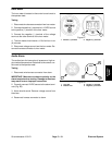
Glow Controller
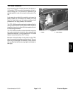
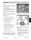
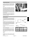
The glow controller is located under the console cover
(Fig. 39).
NOTE: Refer to electrical schematic and circuit draw-
ings in Chapter 9 -- Foldout Drawings when trouble-
shooting the glow controller.
Glow Controller Operation
1. When the ignition switch is placed in the ON position,
the controller energizes the glow plugs and lights up the
glow lamp for approximately 10 seconds.
2. When the ignition switch is held in the START posi-
tion, the glow plugs will energize and the glow lamp will
not light.
3. When the ignition switch is released from START to
ON, the glow plugs will deenergize and the glow lamp
will remain off.
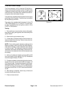
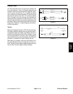
Glow Controller Checks
1. Make sure there is power from the battery.
2. Disconnectelectrical connector to the engine run so-
lenoid to prevent the engine from starting.
3. Placeignition switch in theONposition. Verify thefol-
lowing while in the ON position:
A. Glow indicator lamp is illuminated.
B. Glow relay is energized.
C. Glow plugs are energized.
D. Glow indicator lamp goes out and glow plugs de--
energize after approximately 10 seconds.
4. Place ignition switch in the START position. Verify
the following while in the START position:
A. Glow indicator lamp is not illuminated.
B. Glow relay is energized.
C. Glow plugs are energized.
D. Power exists at terminal 1 of the glow controller.
NOTE: Ifthere is no power at terminal 1 oftheglowcon-
troller, verify continuity of the circuitry from the ignition
switch to the controller and perform step 4 again (see
electrical schematic in Chapter 9 -- Foldout Drawings).
1. Control panel 2. Controller location
Figure 39
1
2
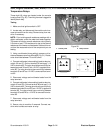
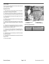
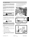
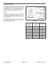
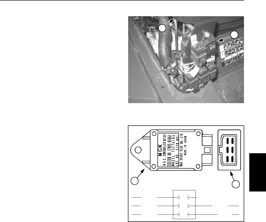
1. Glow controller end view 2. Controller side view
Figure 40
3
2
1
6
4
5
2
1
TEMP (not used)
GLOW
GROUND
VIOLET
+12V
LAMP
START
BROWN
BLACK
YELLOW
ORANGE
CONTROLLER
1
2
3
4
5
6
CONNECTIONS
5. If any of the conditions in step 3 are not met or power
to terminal 1 exists and any of the other conditions in
step 4 are not met:
A. Verify continuity of the circuitry from the batteryto
the glow relay and glow plugs (see electrical sche-
matic in Chapter 9 -- Foldout Drawings).
B. Verify continuity of the circuitry from the batteryto
ignition switch, glow controller, glow lamp, glow relay
and ground (see electrical schematic in Chapter 9 --
Foldout Drawings).
C. Replace parts as necessary.
6. Connect electrical connector to the run solenoid.
Electrical
System