


Groundsmaster 4100--D Page 3 -- 17 Kubota Diesel Engine
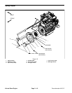
Coupler Removal (Fig. 16)
NOTE: The hydraulic pump assembly needs to be re-
moved from engine before coupler can be r emoved.
1. If engine is in machine, support engine from below to
prevent it from shifting while removing hydraulic pump
assembly (see Piston (Traction) Pump Removal in the
Service and Repairs section of Chapter 4 -- Hydraulic
System), transport cylinder assembly, flywheel plate,
engine mounts and spring coupler.
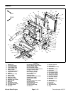
2. Remove flywheel plate and spring coupler from en-
gine using Figure 16 as a guide.
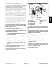
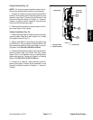
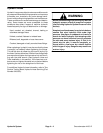
Coupler Installation (Fig. 16)
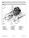
1. Position spring coupler to engine flywheel and align
mounting holes. Make sure that coupler hub is away
from engine flywheel (Fig. 17).
2. Apply Loctite #242 (or equivalent) to threads of cap
screws (item 3). Secure coupler to flywheel with six (6)
cap screws and washers. Torque cap screws in a cross-
ing pattern from 29 to 33 ft-- lb (40 to 44 N--m).
3. Positionflywheel plate to engine and enginemounts.
Secure flywheel plate and mounts with cap screws
(items 5 and 7) and washers using a crossing pattern
tightening procedure. Torque cap screws in a crossing
pattern from 28 to 32 ft--lb (38 to 43 N--m).
4. If engine is in machine, install hydraulic pump as-
sembly (see Piston (Traction) Pump Installation in the
Service and Repairs section of Chapter 4 -- Hydraulic
System).
Figure 17
1. Spring coupler
2. Engine flywheel
3. Coupler hub
Engine Side Hydraulic
Pump Side
1
2
3
Kubota
Diesel Engine