


Groundsmaster 4100--D Page 5 -- 11 Electrical System
Component Testing
For accurate resistance and/or continuity checks, elec-
trically disconnect the component being tested from the
circuit (e.g. unplug the ignition switch connector before
doing a continuity check).
NOTE: For engine component testing information, see
the Kubota Workshop Manual, Diesel Engine,
V2403--M--T--E3B Series at the end of Chapter 3 -- Ku-
bota Diesel Engine.
CAUTION
When testing electrical components for continu-
ity with a multimeter (ohms setting), make sure
that power to the circuit has been disconnected.
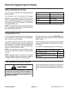
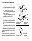
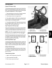
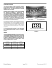
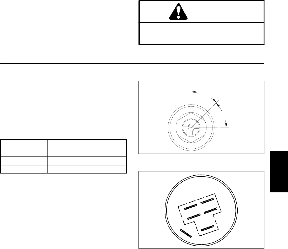
Ignition Switch
The ignition (key) switch has three positions: OFF, ON/
PREHEAT and START (Fig. 11). The terminals are
marked as shown in Figure 12. The circuit wiring of the
ignition switch is shown in the chart. With the use of a
multimeter (ohms setting), the switch functions may be
tested to determine whether continuity exists between
the various terminals for each position. Verify continuity
between switch terminals.
POSITION
CIRCUIT
OFF NONE
ON / PREHEAT B+I+A, X+Y
START B+I+S
Figure 11
45
°
ON / PREHEAT
START
OFF
45
°
Figure 12
A
B
S
Y
X
I
Electrical
System