


Groundsmaster 4100--D Hydraulic SystemPage 4 -- 119
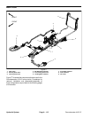
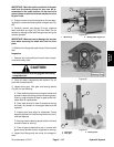
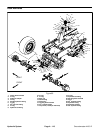
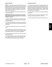
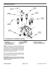
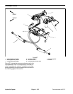
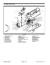
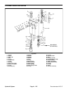
Removal (Fig. 85)
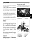
NOTE: The ports on the manifold are marked for easy
identification of components. Example: SV1 is the deck
solenoid valve and P1 is a gear pump connection port.
(See Hydraulic Schematic in Chapter 9 -- Foldout Draw-
ings toidentifythe function ofthe hydraulic lines andcar-
tridge valves at each port).
The control manifolds for the three (3) cutting deck sec-
tions are very similar.
IMPORTANT: Whenservicingthedeckcontrolman-
ifolds, DO NOT interchange parts from one control
manifold to another.
1. Read the General Precautions for Removing and
Installing Hydraulic System Components at the begin-
ning of this section.
2. To prevent contamination ofhydraulic system during
manifold removal, thoroughly clean exterior of manifold
and fittings.
3. Disconnect electrical connector from the solenoid
valve.
4. Disconnect hydraulic lines from manifold and put
caps or plugs on open hydraulic lines and fittings. Label
disconnected hydraulic lines for proper installation.
5. Remove hydraulic manifold from the frame using
Figure 85 as guide.
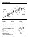
6. If hydraulic fittings are to be removed from manifold,
mark fitting orientation to allow correct assembly. Re-
move fittings from manifold and discard O--rings.
Installation (Fig. 85)
1. If fittings were removed from manifold, lubricate and
place new O--rings onto fittings. Install fittings into man-
ifold openings using marks made during the removal
process to properly orientate fittings. Tighten fittings
(see Hydraulic Fitting Installation in the General Infor-
mation section of this chapter).
2. Install hydraulic manifold to the frame using Figure
85 as guide.
3. Remove caps and plugs from fittings and hoses.
Properly connect hydraulic lines to manifold.
4. Connect electrical connector to the solenoid valve.
Hydraulic
System