


Groundsmaster 4100--DPage 6 -- 26Axles, Planetaries and Brakes
Differential Gear
The following procedures assume the rear axle assem-
bly has been removed from the machine (see Rear Axle
Assembly Removal in this section).
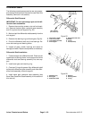
Differential Gear Removal
1. Remove bevel gear case/axle case assemblies (see
Bevel Gear Case/Axle Case Assembly in this section of
this manual).
IMPORTANT: Do not interchange right and left dif-
ferential shafts assemblies.
2. Mark and pull the differential shaft assemblies from
the axle support.
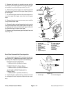
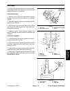
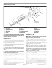
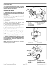
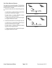
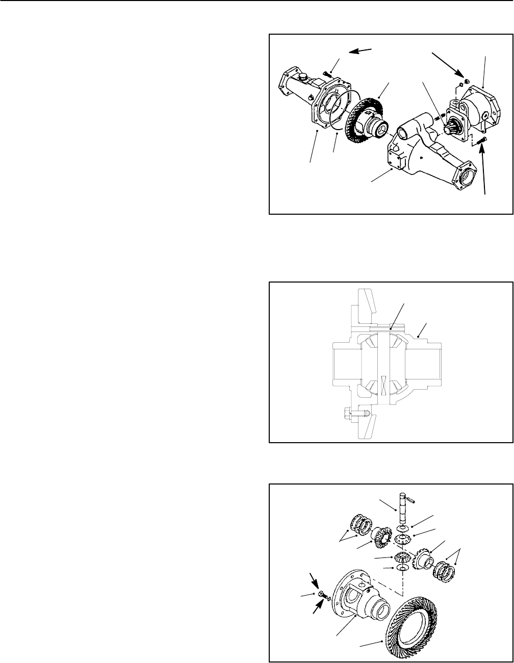
3. Remove input shaft/pinion gear assembly, shims
and O-ring from the axle support (Fig. 34).
4. Remove the axle support case screws. Separate the
axle support halves and remove the O-ring.
5. Removethe differential gearassembly,bearingsand
adjusting shims from the axle case.
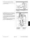
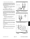
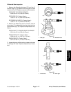
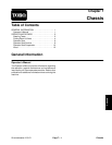
6. Drive the spring pin from the differential case with a
punch and hammer. Discard the spring pin (Fig. 35).
NOTE: Mark and arrange all components so they can
be reassembled in their original position.
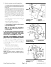
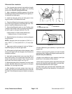
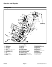
7. Remove the differential pinion shaft, pinion gears
and pinion washers. Remove the differential side gears
and side gear shims. Remove the ring gear only if it will
be replaced (Fig. 36).
NOTE: Replacement ring gears are only available in
matched ring and pinion sets.
1. Gear Case
2. Pinion Gear
3. Axle support (left)
4. Axle support (right)
5. Case screw (8 used)
6. Differential gear
7. O-ring
Figure 34
1
3
4
5
6
7
2
35 to 41 ft--lb
(47to56N--m)
35 to 41 ft--lb
(47to56N--m)
1. Differential case 2. Spring pin
Figure 35
1
2
1. Differential pinion shaft
2. Pinion gear
3. Pinion washer
4. Side gear
5. Side gear shims
6. Ring gear
7. Differential case
8. Bolt/washer (8 used)
1
Figure 36
2
3
4
5
6
7
3
2
4
5
22 to 25 ft--lb
(30to34N--m)
Threadlocking
Compound
8