


Greensmaster 3150 Hydraulic SystemPage 4 -- 69
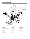
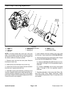
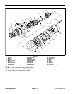
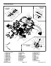
Front Wheel Motor Removal (Fig. 49)
1. Before removing any parts from the hydraulic sys-
tem, park the machine on a level surface, engage the
parking brake, lower the cutting units and stop the en-
gine.
2. Remove front wheel, brake drum assembly and
brake assembly from machine (see Front Wheel and
Brake in the Service and Repairs section of Chapter 6
-- Chassis).
CAUTION
Before continuing further, read and become fa -
miliar with General Precautions for Removing
and Installing Hydraulic System Components.
3. Label all wheel motor hydraulic connections for as-
sembly purposes.
4. Disconnect both hose assemblies and O--rings from
the hydraulic fittings on the wheel motor. Allow hoses to
drain into a suitable container. Discard removed O--
rings.
5. Mark wheel motor fitting orientation to allow correct
assembly. Remove hydraulic fittings and O--rings from
motor. Discard removed O--rings.
6. Put caps or plugs on disconnected hoses and motor
port openings to prevent contamination.
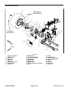
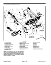
7. Remove four (4) cap screws (item 21) and lock nuts
(item 22) that secure brake bracket (item 14) and hy-
draulic wheel motor t o machine. Remove brake bracket
and motor from the frame.
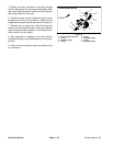
Front Wheel Motor Installation (Fig. 49)
1. Position hydraulic wheel motor and brake bracket
(item 14) to the frame. Make sure ports of motor face the
rear of the machine. Secure motor and brake bracket to
the frame with four (4) cap screws (item 21) and lock
nuts (item 22).
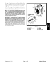
2. Remove plugs from wheel motor ports. Lubricate
and place new O--rings onto fittings. Install fittings into
motor openings making sure that fitting orientation is as
noted during removal. Tightenfittings (see Hydraulic Fit-
ting Installation inthe General Informationsec tion of this
chapter).
3. Remove caps from disconnected hydraulic lines.
4. Lubricate and position new O--rings to fittings on
wheel motor. Use labels placed during the removal pro-
cess to properly install hydraulic lines to wheel motor fit-
tings (see Hydraulic Hose andTubeInstallationinthe
General Information section of this chapter).
5. Install brake assembly, brake drum assembly and
front wheel to machine (see Front Wheel and Brake in
the Service and Repairs section of Chapter 6 -- Chas-
sis).
Failure t o maintain proper wheel lug nut and
wheel hub lock nut torque could result in failure
or loss of wheel and may result in personal injury.
WARNING
6. Make sure to properly torque lock nut from 250 to
400 ft--l b (339 to 542 N--m) and wheel lug nuts from 70
to 90 ft--lb (95 to 122 N--m).
7. Check oil level in hydraulic reservoir and add correct
oil if necessary.
8. Follow Hydraulic System Start--up procedures (see
Hydraulic System Start--up in this section).
Hydraulic
System