


Greensmaster 3150 Page 6 -- 11 Chassis
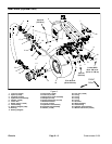
Assembly (Fig. 7)
1. If drive studs (item 4) were removed, press new
studs fully to the shoulder of the wheel hub.
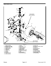
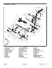
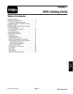
NOTE: Arrow on the side of the clutch roller bearings
(item 3) must point to the long side of the end of the hub.
2. Press clutch roller bearings (item 3) into the hub as
follows (Fig. 9):
A. Press three (3) roller bearings into flange end of
the hub. The outer edge of the third bearing must be
flush with t he recessed edge within the hub.
B. Press final roller bearing into opposite end of hub.
The outer edge of the bearing must be flush with the
recessed edge within the hub.
C. The installed bearings must not interfere with
grease fitt ing hole in the hub.
3. Grease inner edge of the new grease seals (item 9)
with No. 2 multipurpose lithium base grease. Slide one
(1) seal onto motor shaft past groove closest to t he mo-
tor. Install snap ring (item 8) into groove.
4. Slide flat washer (item 7) and two (2) thrust washers
(item 6) onto the motor shaft. Slide hub onto the shaft
with the short end first.
5. Slide remaining thrust washers (item 6) and flat
washer (item 7) onto the motor shaft. Install remaining
snap ring (item 8) into the shaft groove. Slide remaining
new grease seal (item 9) onto motor shaft.
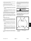
IMPORTANT: The hub should spin freely in the for-
ward direction, but lock on the hydraulic motor
shaft when it is rotated in the reverse direction.
6. Press grease seals (item 9) into the hub so they are
flushwiththeendofthehub.
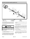
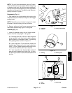
7. Lubricate and position new O--rings to fittings on hy -
draulic motor. Use labels p laced during the removal pro-
cess to properly install hydraulic hoses to motor
adapters (see Hydraulic Hose and Tube Installation in
the General Information section of Chapter 4 -- Hydrau-
lic System).
8. Install rear wheel hub and motor assembly to rear
castor fork of machine (see Rear Wheel (Optional 3WD)
in this section).
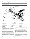
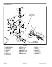
1. Hub and motor assembly
2. O--ring
3. Adapter
4. O--ring
5. Hydraulic hose
6. Hydraulic hose
Figure 8
3
4
1
2
2
3
4
5
6
Figure 9
ARROWS ON BEARING
TOWARDS LONG END
OUTER BEARING EDGE
MUSTBEFLUSHWITHEDGE
Chassis