


Greensmaster 3150 Page 5 -- 17 Electrical System
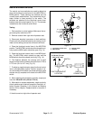
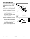
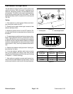
Joystick Raise and Lower Switches
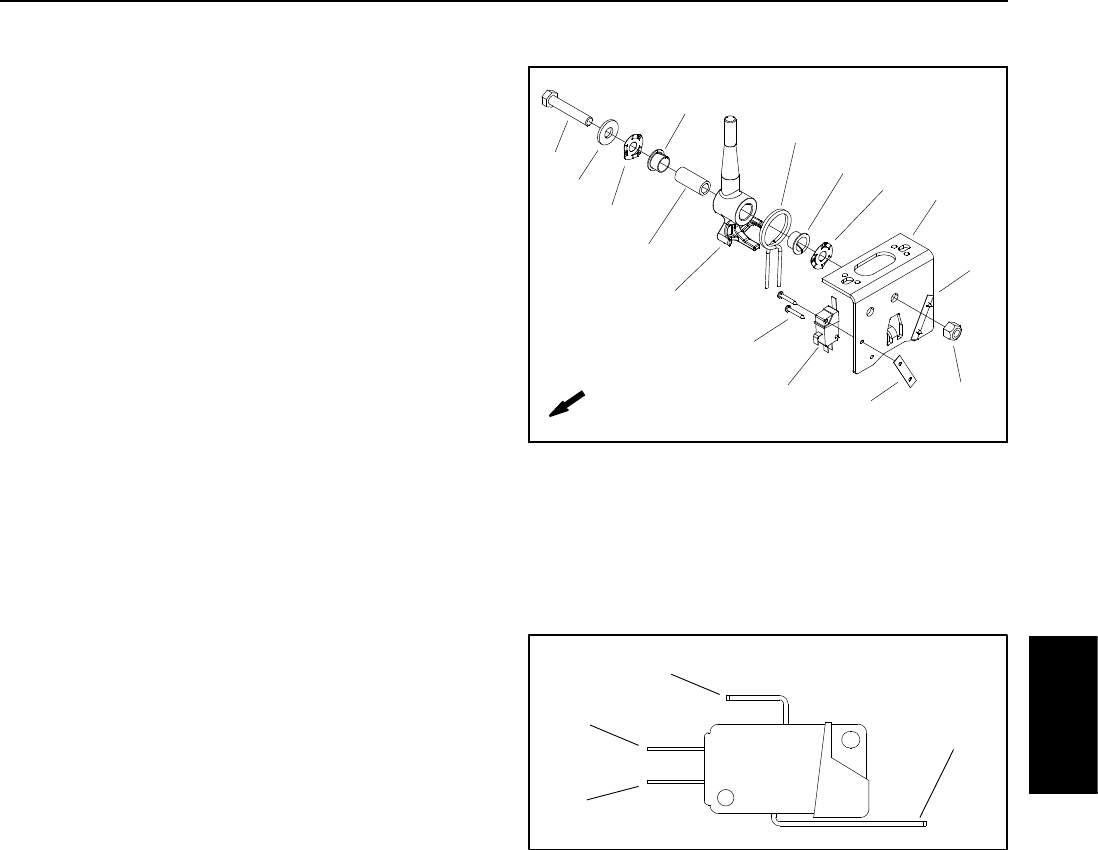
The joystick raise and lower switches are located on the
lift control mechanism. The rear switch is u sed to lower
the reels and the front switch to raise them(Fig. 17). The
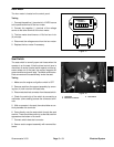
switches are identical and are shown in Figure 18.
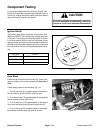
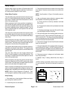
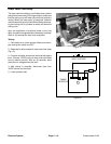
Testing
1. Make sure the engine and ignition switch are OFF.
Remove the plastic cover and disconnect the harness
connectors from the joystick switches.
2. Check the continuity of the raise switch by connect-
ing a multimeter (ohms setting) across the switch con-
nector terminals as follows:
A. With the joystick in the rest position, continuity
should only exist between the common and NC ter-
minals (blue and green/black wires).
B. With the joystick in the raise position, continuity
should only exist between the common and NO ter-
minals (blue and green/gray wires).
3. Check the continuity of the lower switch by connect-
ing a multimeter (ohms setting) across the switch con-
nector terminals as follows:
A. With the joystick in the rest position, continuity
should only exist between the common and NC ter-
minals (open terminal and green/black wires).
B. With the joystick in the lower position, continuity
should only exist between the common and NO ter-
minals (green/black and gray/black wires).
4. After testing, connect the harness connectors to the
joystick switches and reinstall the plastic cover.
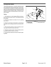
Figure 17
2
3
6
8
9
10
11
13
1
5
7
12
4
3
4
FRONT
1. Cap screw
2. Flat washer
3. Spring washer (2 used)
4. Bushing ( 2 used)
5. Spacer
6. Joystick
7. Spring
8. Screw (4 used)
9. Raise switch
10. Speed nut (2 used)
11. Lower switch
12. Joystick bracket
13. Lock nut
1. Common terminal
2. NO terminal
3. NC terminal
4. Switch lever
Figure 18
1
2
3
4
Electrical
System