Greensmaster 3150Hydraulic System Page 4 -- 92
Rotary Cartridge Valve
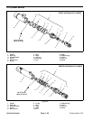
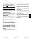
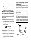
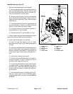
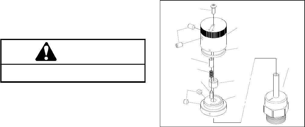
1. Remove rotary handle from valve (Fig. 68):
A. Loosen two (2) set screws that secure handle
cap.
B. Remove screw and then lift handle cap from
valve.
C. Locate and retrieve detent pin, compression
spring, bushing and lip seal. The sleeve bearing
should stay in the cap.
D. Loosen two (2) set screws that secure handle
base to flow control valve and remove base.
IMPORTANT: Use care wh en removing the rotary
cartridge valve. Slight bending or distortion of the
stemtube can cause bindingand malfunction. Make
sure that deep well socket fully engages the valve
base.
2. Make sure manifold is clean before removing the
rotary cartridge valve. Remove cartridge valve from
manifold with a deep well socket. Note location of O--
rings and backup rings on valve. Remove and discard
removed seal kit.
3. Visually inspectthe manifold port and cartridgevalve
for damage to sealing surfaces, damaged threads and
contamination.
A. Contamination may cause valves to stick or hang
up, it can become lodged in small valve orifices or
seal areas causing valve malfunction.
B. If sealing surfaces appear pitted or damaged, the
hydraulic system may be overheating or there may
be water in the system.
CAUTION
Use eye protection such as goggles when using
compressed air.
4. If necessary, clean cartridge valve using clean min-
eral spirits. Submerge valve in clean mineral spirits to
flush out contamination. Pa rticles as fine as talcumpow-
der can affect the operation of high pressure hydraulic
valves. Clean and dry with compressed air.
5. Reinstall rotary cartridge valve into manifold port:
A. Lubricate new O-rings and backup rings of seal
kit with clean hydraulic oil and install. The O-rings
and backup rings of seal kit must be arranged prop-
erly on the cartridge valve for proper operation and
sealing.
IMPORTANT: Use care when installing the rotary
cartridge valve. Slight bending or distortion of
the stem tube can cause binding and malfunc-
tion. Make sure that deep well socket fully en-
gages the valve base.
B. Lubricate threads on cartridge valve with clean
hydraulic oil. Thread rotary cartridge valve carefully
into the manifold port. The valve should go in easily
without binding. Torque valve to specification shown
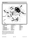
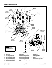
in Figure 67.
6. Install rotary handle (Fig. 68):
A. Place handle base onflow control valve and posi-
tion alignment mark on base with number 1 on man-
ifold. Secure base with two (2) set screws. Apply a
light coating of grease to chamfer on top of base to
ease seal installation.
B. Make sure that sleeve bearing is in handle cap. If
necessary, press sleeve bearing into cap. Install lip
seal on cap with seal lip facing down.
C. While pressing on the cap to keep the lip seal in
place, rotate cap in a clockwise direction until the ar-
row on the cap aligns with number 1 on t he manifold.
By rotating the cap clockwise, the valve will remain
closed. Install screw to retain cap.
D. Make sure that alignment marks on cap and base
are in lineand that arrow on cap is pointing tonumber
1 on manifold. Tighten two (2) set screws to secure
handle cap.
1. Handle Base
2. Handle Cap
3. Detent Pin
4. Compression Spring
5. Bushing
6. Set Screw (2 used)
7. Set Screw (2 used)
8. Screw
9. Lip Seal
10. Sleeve Bearing
11. Flow Control Valve
6
5
4
7
9
10
3
2
8
1
11
Figure 68


