


Greensmaster 3150 Page 6 -- 9 Chassis
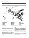
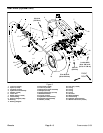
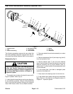
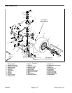
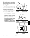
Removal (Fig. 6)
1. Park machine on a level surface. Make sure engine
is off. Set brake and block front wheels.
2. Loosen, but do not remove, lug nuts (item 18).
3. Chockb oth frontwheels toprevent the machine f rom
moving.
4. Usea jack or hoist to lift rear wheel off the ground and
then place appropriate jackstands beneath the frame to
support the raised machine.
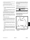
CAUTION
Support wheel (item 28) and motor and hub as-
sembly (item 14) to prevent dropping the assem-
bly and causing personal injury.
5. Support rear wheel, hydraulic motor and hub assem-
bly to prevent it from falling.
6. Remove wheel (item 28) and hydraulic motor and
hub assembly (item 1 4) from the castor fork (item 6) as
follows:
A. Remove cap screws(item 12), lock nuts (item 22)
and washers (item 21) securing flangettes (items 9
and 11) and mount spacers (item 7) to castor fork.
B. Remove both socket head screws (item 16) and
lock nuts (item 13) securing the hydraulic motor and
hub assembly to the castor fork.
C. Lower wheel and hydraulic motor and hub as-
sembly from the castor fork.
7. Loosen set screw (item 27) on bearing (item 10). Pull
flangettes (items 9 and11) and bearing from the hydrau-
lic motor shaft.
8. Remove grease fitting (item 8) from the hydraulic
motor and hub assembly. Remove four (4) lug nuts (item
18) and wheel (item 28) from the hub drive studs.
NOTE: If wheel hub and motor assembly need to be
serviced, see Rear Wheel Hub and Motor Assembly
(Optional 3WD) in this section. If castor fork removal is
necessary, see Rear Castor Fork in this section.
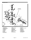
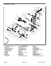
Installation (Fig. 6)
1. Secure wheel (item 28) to the drive studs of the hy-
draulic motor and hub assembly with four (4) lug nuts
(item 18). Torque nuts from 70 to 90 ft--lb (95 to 122
N--m).
2. Reinstall grease f itting (item 8) into hydraulic motor
and hub a ssembly so it points away from the wheel.
3. Install flangette (item 11), bearing (item 10) and re-
lube flangette (item 9) onto the motor shaft.
4. Position hy draulic motor and hub assembly, flan-
gettes with bearing and wheel into the castor fork. Make
sure hose fittings on the motor face to the rear.
5. Loosely secure hydraulic motor andhub assembly to
the right inside of the castor fork with both socket head
screws (item 16) and lock nuts (item 13).
6. Position flangette grease fitting facing downward.
Then, loosely secure flangettes (items 9 and 11) and
bearing (item 10) to the left inside of the castor fork with
cap screws (item 12), mount spacers (item 7), washers
(item 21) and lock nuts (item 22).
7. Secure wheel (item 28) and hydraulic motor and hub
assembly (item 14) to the castor fork:
A. Torque socket head screws (item 16) to 100 ft--lb
(135 N--m).
B. Torque cap screws (item 12) to 40 ft--lb (55N--m).
8. Apply loctite to bearing set screw (item 27). Torque
set screw from 80 to 100 in--lb (9.0 to 11.3 N--m).
9. Lower machine to the ground. Check that lug nuts
are properly torqued from 70 to 90 ft--lb (95 to 122
N--m).
Chassis