Greensmaster 3150Page 5 -- 26Electrical System
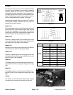
Leak Detector Float Sensor
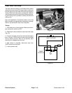
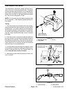
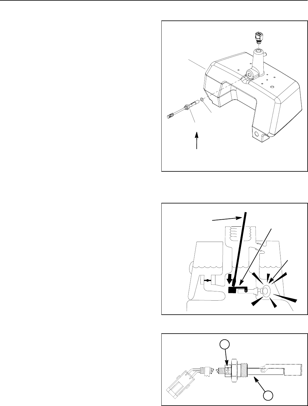
The leak detector float sensor closely monitors the hy -
draulic fluid level in the main hydraulic tank. The sensor
contacts are open when the float is in the raised position
and oil level in the hydraulic tank is correct. The sensor
closes when the float is in the lowered position caused
by a low oil level and potential oil leak.
NOTE: For information on leak detector operation refer
to Turf Guardiant Leak Dete ctor System Operation in
this chapter.
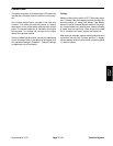
Testing
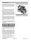
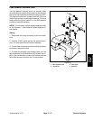
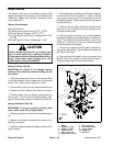
1. If the float sensor is connected to the main harness,
remove hydraulic tank cap and screen from filler neck of
hydraulic tank. Turn ignition switch to the RUN position
(do not start the engine). Insert aclean rodor screw driv-
er into filler neck and gently push down on sensor float
(Fig. 33). Alarm should sound after a one (1) second
time delay.
2. If the float sensor is removed or disconnected from
the main harness, connect a continuity tester across the
float sensor wire terminals. There should be continuity
acrossthe terminals only when the float is pushed down.
There should be no continuity across the terminals
when the float is in the raised position.
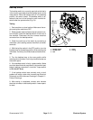
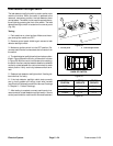
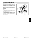
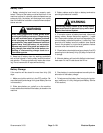
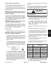
3. If oil level sensor was removed from reservoir, install
oil level sensor into reservoir making sure that arrow on
sensor is pointing down (Fig. 34). Torque sensor nut
from 110to140in--lb(12.5to15.8N--m).
4. After testing, make sure that hydraulic oil level in res-
ervoir is correct.
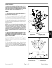
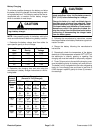
Figure 32
1. Main hydraulic tank
2. Float sensor
3. O--ring
110 to 140 in--lb
(12.5 to 15.8 N--m)
2
3
1
Figure 33
ALARM
(on)
FLOAT SENSOR
(lowered/closed)
CLEAN ROD OR
SCREWDRIVER
1. Oil level sensor 2. Sensor arrow
Figure 34
1
2


