


Greensmaster 3150 Hydraulic SystemPage 4 -- 47
NOTE: The steering wheel must be able to turn with no
more than 45 in-- lb (5.1 N--m) of torque.
5. Perform the Implement Relief Valve Pressure and
Gear Pump (Rear Section) Flow tests to make sure that
relief valve and gear pump are functioning correctly.
NOTE: This steering test procedure will be affected by
incorrect rear tire pressure, binding in the hydraulic
steering cylinder, extra weight on the vehicle and/or
binding of the steering fork assembly. Make sure that
these items are checked before proceeding with any hy-
draulic testing procedure.
6. If either of these performance tests indicate a steer-
ing problem, determine if the steering cylinder is faulty
using the following procedure.
A. Park machine on a level surface with the cutting
units lowered and off. Apply the parking brake.
B. Turn the steering wheel all the way to the right
(clockwise) so the steering cylinder rod is fully ex-
tended.
C. Turn engine off.
CAUTION
Before continuing further, read and become fa -
miliar with Precautions for Hydraulic Testing.
D. Read Precautions for Hydraulic Testing.
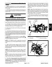
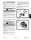
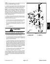
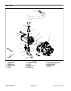
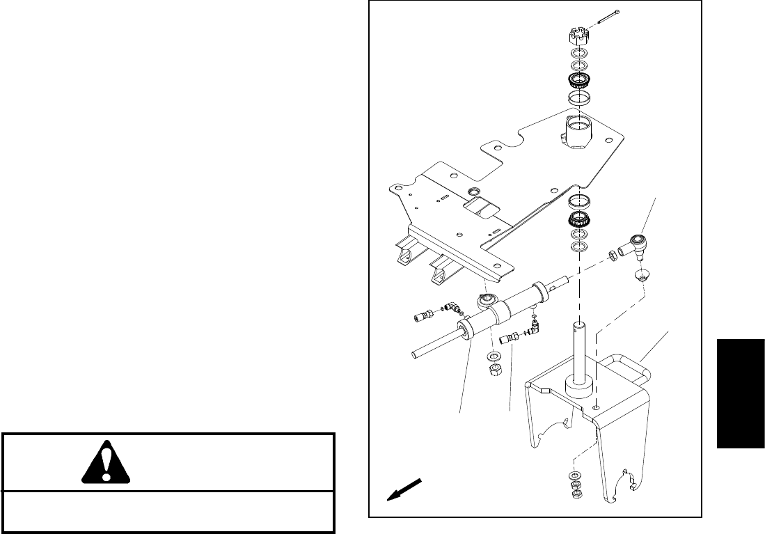
E. Remove hydraulic hose from the 90
o
fitting on the
rod end of the steering cylinder (Fig. 31). Install steel
plug in the end of the hose.
F. With the engine o ff, continue turning the steering
wheel to the right (clockwise) with the steering cylin-
der fully extended. Observe the open fitting on the
steering cylinder as the steering wheel isturned. If oil
comes out of the fitting while turning the steering
wheel to the right, the steering cylinder has internal
leakage and must be repaired or replaced.
G. Remove plug from the hydraulic hose. Recon-
nect hose to the steering cylinder fitting.
7. If steering problem exists and steering cylinder
tested acceptably, steering control valve requires ser-
vice (see Steering Control Valve and Steering Control
Valve Service in the Service and Repairs section of this
chapter).
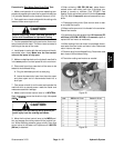
1. Steering cylinder
2. Hydraulic hose
3. Rod end
4. Castor fork
Figure 31
FRONT
3
1
2
4
Hydraulic
System