


Greensmaster 3150Page 6 -- 10Chassis
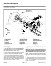
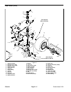
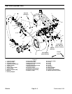
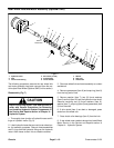
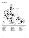
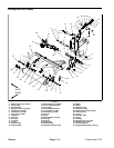
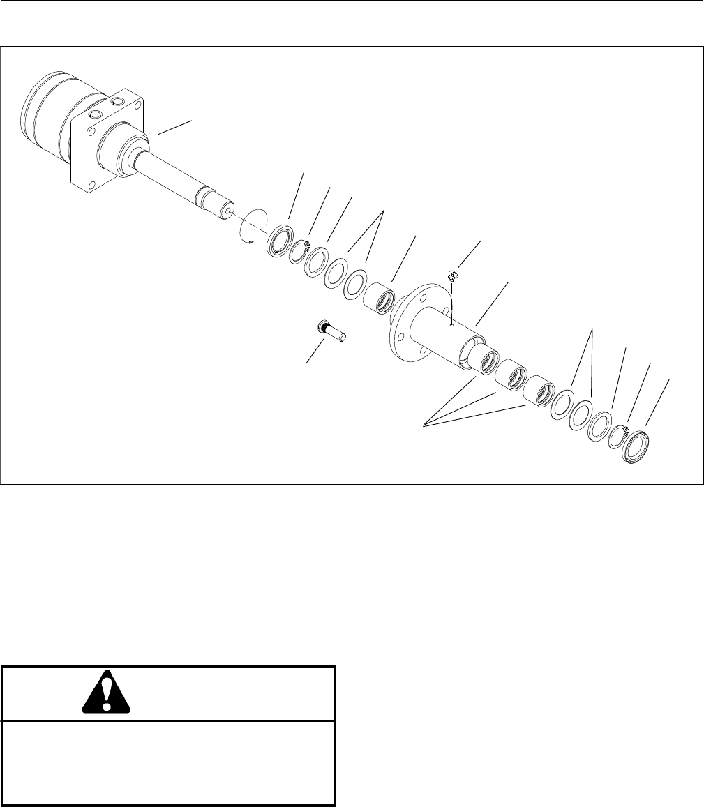
Rear Wheel Hub and Motor Assembly (Optional 3WD)
1. Hydraulic motor
2. Hub
3. Clutch roller bearing
4. Drive stud (4 used)
5. Grease fitting
6. Thrust washer
7. Washer
8. Snap ring
9. Grease seal
Figure 7
1
9
3
4
6
5
2
6
7
8
9
FREE
ROTA
TION
3
8
7
The following procedures assume the rear wheel hub
and motor assembly has been removed from the ma-
chine (see Rea r Wheel (Optional 3WD) in this section).
Disassembly (Fig. 7)
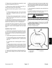
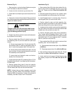
CAUTION
Before continuing further, read and become fa-
miliar with General Precautions for Removing
and Installing Hydraulic System Components in
the Service and Repairs section of Chapter 4 --
Hydraulic System.
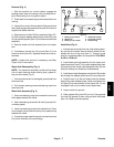
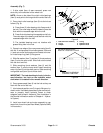
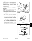
1. Thoroughly clean junction of hydraulic hoses and fit-
tings on hydraulic motor (Fig. 8).
2. Label hydraulic hoses that connect to rear wheel mo-
tor for as sembly purposes. Remove hose assemblies
and O--rings from the hydraulic fittings on the hydraulic
motor. Allow hoses to drain into a suitable container.
3. Placerear wheel hub and motorassembly on aclean
workbench.
4. Remove grease seal (item 9) and snap ring (item 8)
from the long end of hub.
5. Remove washer (item 7), two (2) thrust washers
(item 6) and hub (item 2) from the hydraulic motor shaft.
Remove remaining two (2) thrust washers (item 6),
washer (item 7), snapring (item8) and grease seal (item
9) from the shaft.
6. If drive studs (item 4) are bent or damaged, press
studs from the wheel hub.
7. Press clutch roller bearings (item 3) from the h ub.
8. If rear wheel motor needs to be serviced, see Wheel
Motor Service in the Service and Repairs section of
Chapter 4 -- Hydraulic System.