


Greensmaster 3150 Hydraulic SystemPage 4 -- 107
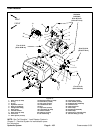
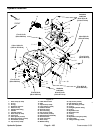
Removing Hydraulic Reservoir (Fig. 79)
1. Before removing any parts from the hydraulic sys-
tem, park machine on a level surface, set brake, lower
cutting units and stop engine.
CAUTION
Before continuing further, read and become fa -
miliar with General Precautions for Removing
and Installing Hydraulic System Components.
2. Remove leak detector assembly (see Leak Detector
in this section).
3. Drain remaining hydraulic oil from hydraulic reser-
voir through pump inlet hose into a suitable container.
4. Unplug wire harness connector from oil level sensor
(item 20).
5. Labelall hydraulic reservoir hose connections for as-
sembly purposes.
6. Remove hose assemblies from reservoir hydraulic
fittings. Allow hoses to drain into a suitable container.
7. Remove three (3) cap screws (item 29), flat washers
(item 30) and bushings (41) securing the hydraulic
reservoir to the machine frame.
8. Remove hydraulic reservoir from machine.
9. Remove hydraulic fittings and oil level sensor from
hydraulic reservoir if necessary.
Inspecting Reservoir Parts (Fig. 79)
1. Clean reservoir a nd filler screen with solvent.
2. Inspect reservoir for leaks, cracks or other damage.
3. Replace hydraulic hoses if worn or leaking.
Installing Hydraulic Reservoir (Fig. 79)
1. Install all removed hydraulic fittings into hydraulic
reservoir ports. Torque fittings to values shown in Figure
79.
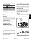
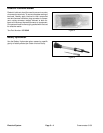
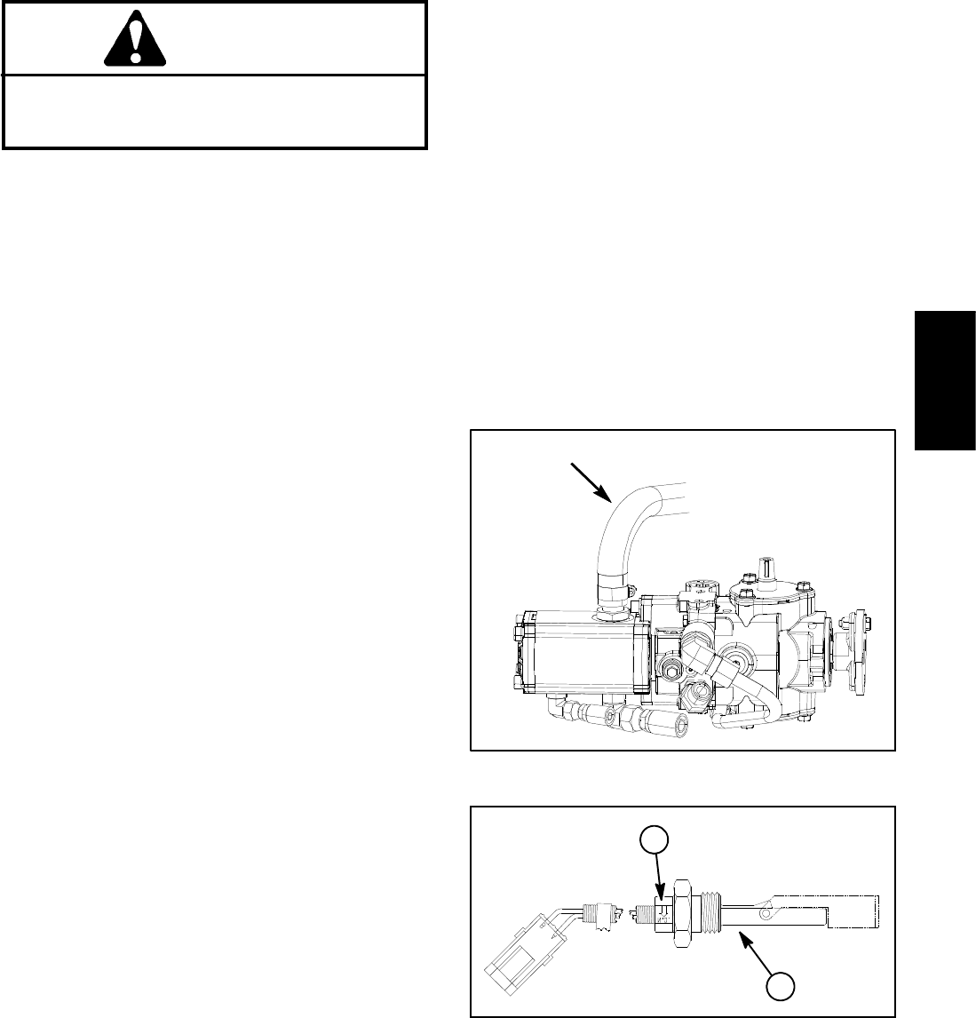
2. If oil level sensor was removed from reservoir, install
sensor in reservoir making sure that a rrow on sensor is
pointing down (Fig. 81). Torque sensor nut from 110 to
140 in--lb (12.5 to 15.8 N--m).
3. Position hydraulic reservoir onto the machine frame.
IMPORTANT: After hydraulic reservoir is installed,
make sure that clearance between hydraulic reser-
voir and fuel tank if from 0.125” to 0.375” (3.2 to 9.5
mm).
4. Apply antiseize lubricant to threads of three (3) cap
screws (item 29). Secure hydraulic reservoir to the ma-
chine frame with three (3) cap screws, flatwashers (item
30) and bushings (item 41). Torque cap screws from 30
to 60 in--lb (3.4 to 6.7 N--m).
5. Using notes taken during reservoir removal, connect
hydraulic hoses to the reservoir fittings. Tighten hose
connections (see Hydraulic Hose and Tube Installation
in the General Information section of this chapter).
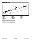
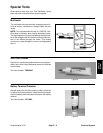
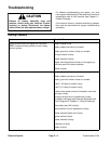
6. Secure pump inlet hose t o gear pump with hose
clamp (Fig. 80).
7. Connect wire harness connector to oil level sensor
(item 20).
8. Install leak detector assembly (see Leak Detector in
this section). Make sure that reservoir oil level is correct.
Figure 80
PUMP INLET HOSE
1. Oil level sensor 2. Sensor arrow
Figure 81
1
2
Hydraulic
System