


Greensmaster 3150 Hydraulic SystemPage 4 -- 33
4. Block up front wheels off the ground (also rear wheel
if machine is equipped with 3WD) to allow flow through
the traction circuit.
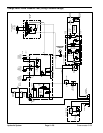
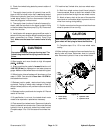
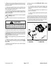
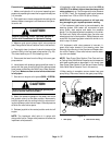
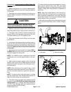
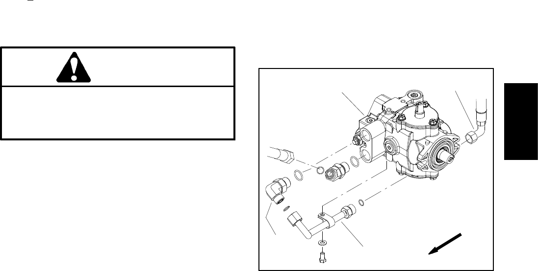
5. Disconnect hydraulic hose from the hydraulic tube
that connects to the upper hydraulic fitting on the front
side of the piston pump (Fig. 21).
6. Install tester in s eries with the pump and the discon-
nected hose. Make sure flow control valve on the
tester is fully open.
7. Start engine and move throttle to high idle speed
(2850 +
50 RPM) position.
8. Move functional control lever to the transport posi-
tion.
CAUTION
The drive wheels will be off the ground and rotat-
ing during this test. Make sure machine is well
supported so it will not move and accidentally
fall to prevent injuring anyone near the machine.
9. Slowly push traction pedal into fully forward position.
10.Have secondperson carefully watch pressure gauge
on tester while slowly closing the flow control valve until
1000 PSI (69 bar) is obtained.Verify with aphototac that
the engine speed has not changed.
NOTE: If engine speed drops, piston pump flow will de-
crease.
11.Obser ve flow gauge. If piston pump is in good condi-
tion, flow indication should be approximately 14.5 GPM
(54.9 LPM).
12.Release traction pedal, open control valve on tester
and turn off engine.
13.Ifflowislessthan12.3 GPM (46.6 LPM), consider
the following:
A. The traction pedal and/or traction speed may
need adjustment (see the Traction Unit Operator’s
Manual).
B.Thepistonpumpneedstoberepairedorre-
placed as necessary.
C. Make necessary repairs before performing addi-
tional tests.
14.If piston pump flow test results are met and a traction
problem exists with m achine, che ck wheel motor effi-
ciency (see Wheel Motor Efficiency Test in this chapter).
15.If testing is complete, disconnect tester from hydrau-
lic tube and hose. Reconnect hose to tube.
1. Piston pump
2. Upper fitting
3. Hydraulic tube
4. Hydraulic hose
Figure 21
1
2
3
4
FRONT
Hydraulic
System