


Greensmaster 3150 GroomerPage 8 -- 13
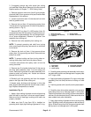
4. Remove grooming reel bearings and seals from
drive plate and support plate assemblies (Fig. 10):
A. Remove seals from groomer plates. Discard re-
moved seals.
B. Press bearings out of side plate housings. Dis-
card removed bearings.
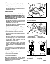
Bearing Installation
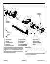
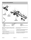
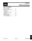
1. Install new grooming reel bearings and seals into
drive plate and support plate assemblies (Fig. 13):
IMPORTANT: Bearings should be installed with ex-
tended inner races toward center of housing. Also,
apply pressure equally to inner and outer bearing
races when installing b earings.
A. Press new outer bearing fully to shoulder of drive
plate bore. Then, install new inner bearing until inner
race contacts outer bearing race.
B. Press new bearing into support plate until it is
flush with shoulder of bearing bore.
C. Install new seals into side plates. NOTE: Seals
should be installed so the lip side of the seal will face
the center of the cutting reel. When bearings are
greased, grease will purge from inner seals.
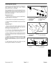
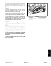
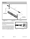
2. Install support plate to right side of cutting unit:
A. Apply antiseize lubricant to threads of RH groom-
er arm lift rod.
B. Position support plate to cutting unit making sure
that RH groomer arm lift rod is po sitioned through
bushing in support plate.
C. Place spring washer and lock nut on lift rod
threads (Fig. 12). Tighten lock nut.
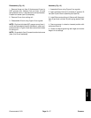
D. Position motor m ount to groomer support plate
(Fig. 11). Secure motor mount and support plate to
cutting unit with two (2) socket head screws and lock
nuts.
3. Install grooming reel, front roller anddrive plate toleft
side of cutting unit (see Grooming Reel Installation in
this section).
4. Check and adjust grooming reel height and mower
height--of--cut settings.
5. Install cutting unit to the machine.
6. Lubricate groomer bearings.
NOTE: After greasing groomer bearings, operate
groomer for 30 seconds, stop machine and wipe any ex-
cess grease from groomer shaft and seals.
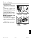
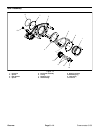
1. Socket head screw
2. Motor mount
3. Groomer side plate (RH)
4. Cutting unit
5. Lock nut (2 used)
Figure 11
4
2
1
3
1
5
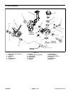
1. Front roller cap screw
2. Grooming reel assembly
3. Lock nut
4. Spring washer
5. Groomer arm lift rod
Figure 12
4
2
1
3
5
1. Outer bearing
2. Drive plate shoulder
3. Inner bearing
4. Inner race
5. Seal lip
6. Support plate bearing
7. Drive plate
8. Support plate
Figure 13
1
2
3
4
5
5
6
8
7
5
Groomer