Greensmaster 3150Groomer Page 8 -- 18
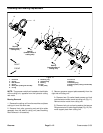
Groomer Brush
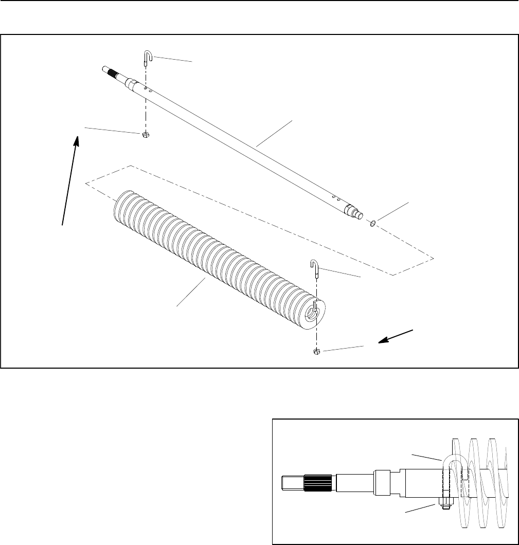
Figure 17
1. Groomer brush shaft
2. Lock nut
3. J--bolt
4. Groomer brush
5. O--ring
20 to 25 in--lb
(2.3 to 2.8 N--m)
20 to 25 in--lb
(2.3 to 2.8 N--m)
3
1
2
4
2
3
5
The groomer brush attaches to the groomer drive in
place of the grooming reel. Removal and installation of
the groomer brush usesthe same procedureas r emoval
and installation of the grooming reel (see Grooming
Reel in this section).
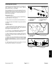
To remove the groomer brush from the shaft, remove the
lock nut and J--bolt from both ends of the brush and slide
the brush from the shaft. When assembling the brush to
the shaft, secure the assembly with J--bolts and lock
nuts. Make sure that the J--bolts are installed with the
threaded portion on the outside of the brush (Fig. 18).
Torque lock nuts from 20 to 25 in--lb (2.3 to 2.8 N--m).
1. J--bolt 2. Lock n ut
Figure 18
2
1


