


Greensmaster 3150Page 5 -- 12Electrical System
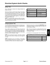
Component Testing
For accurate resistance and/or continuity checks, elec-
trically disconnect the component being tested from the
circuit (e.g. unplug the ignition switch connector before
doing a continuity check on the switch).
CAUTION
When testing electrical components for continu-
ity with a multimeter (ohms setting), make sure
that power to the circuit has been disconnected.
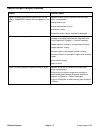
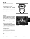
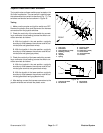
Ignition Switch
The ignition (key) switch has three (3) positions (OFF,
RUN and START). The terminals are marked as shown
in Figure 9. The circuitry of the ignition switch is shown
in the chart below. With the use of a multimeter (ohms
setting),t he swit ch functions may be tested todetermine
whether continuity exists between the various terminals
for each position. Verify continuity between switch termi-
nals.
POSITION
CIRCUIT
OFF NONE
RUN B+I+A, X+Y
START B+I+S
A
B
S
Y
X
I
Figure 9
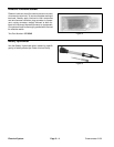
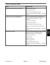
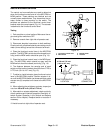
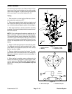
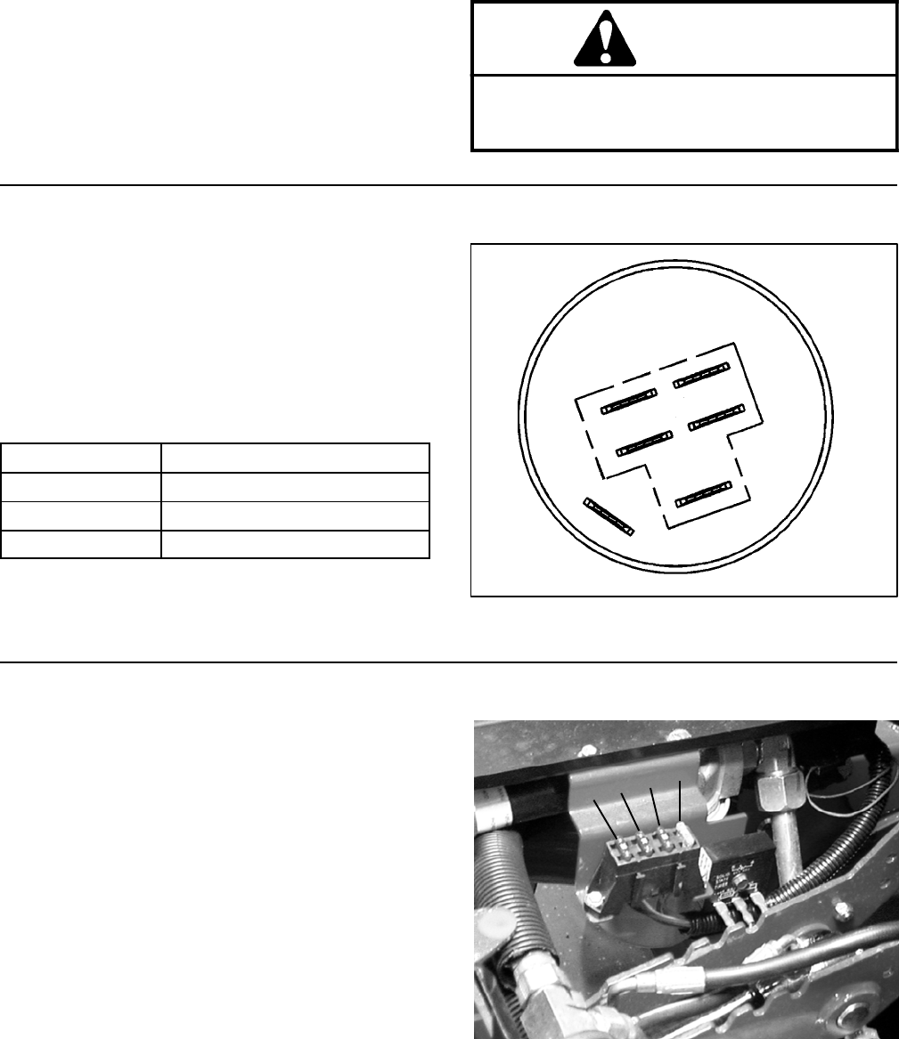
Fuse Block
Fuses can be removed to check continuity. Use a multi-
metertomakesurethatfuseresistanceisless than 1
ohm.
Fuses supply power to the following (Fig. 10):
1. The 20 amp fuse (F1) supplies power to engine run
circuits and also to the hydraulic solenoid coils.
2. The 10 a mp fuse (F2) supplies power to the light/test
switch and the optional light circuit.
3. The 10 amp fuse (F3) supplies power to the engine
run circuits and also to the hydraulic solenoid coils.
4. The 10 amp fuse (F4) supplies power to leak detec-
tor solenoid and the cutting unit control circuits.
Figure 10
F4
F3
F2
F1