


Greensmaster 3150 Hydraulic SystemPage 4 -- 43
Procedure for Mow Circuit Relief Valve (S1R1)
Pres-
sure
Test
1. Make sure hydraulic oil is at normal operating tem-
perature by operating the machine for approximately ten
(10) minutes.
2. Park machine on a levelsurface withthe cutting units
lowered. Make sure engine is off. Make sure thehydrau-
lic tank is full.
CAUTION
Before continuing further, read and become fa -
miliar with Precautions for Hydraulic Testing.
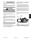
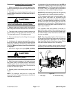
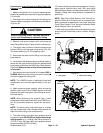
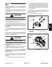
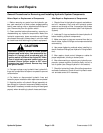
3. Disconnect hydraulic hose from the front fitting of the
left front cutting reel motor (Fig. 27).
4. Install tester with p ressure gauge and flow meter in
series with the disconnected hose and front reel motor
fitting. Make sure the flow control valve on the tester
is fully open.
5. To prevent reel damage, temporarily adjust bedknife
to allow clearance between bedknife and reel (n o con-
tact).
6. Makesure thatreel speed is set tohighest speed set-
ting (fully open) and that backlap knob on the hydraulic
manifold is in the mow position.
CAUTION
Keep away from reels during test to prevent per -
sonal injury from the rotating reel blades.
7. Start engine and move throttle to high idle speed
(2850 +
50 RPM). Engage the cutting units.
8. Watch pressure gauge carefully while slowly closing
the flow control valve on the tester to fully closed.
9. System pressure should be from 2700to3300PSI
(186 to 228 bar) as manifold relief valve (S1R1) opens.
Record test results.
10.After recording mow circuit relief pressure, disen-
gage cutting units. Open controlvalve on tester and shut
off engine.
A. If relief valve pressure is correct, go to step 11.
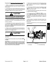
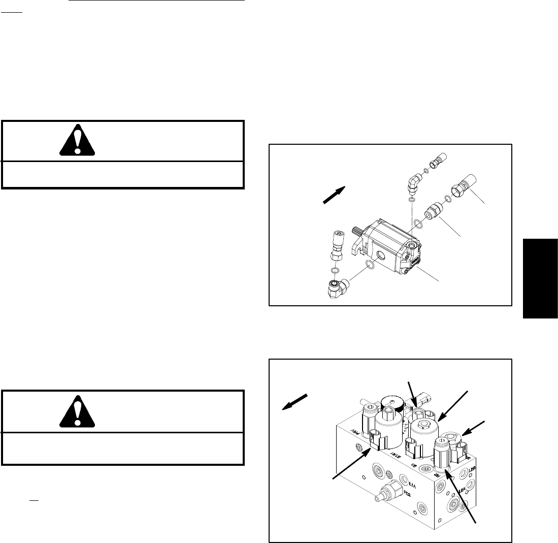
B. If relief valve pressure is not correct, remove so-
lenoid relief valve (S1R1) on hydraulic control man -
ifold (Fig. 28). Clean or replace valve (see Hydraulic
Manifold Service in the Service and Repairs section
of this chapter).After valve service, retest relief valve
(S1R1) pressure.
11.When testing is complete, disconnect tester fr o m
reel motor fitting and hydraulic hose. Reconnect hose to
the front motor fitting.
12.Correctly adjust cutting unit bedknife.
Figure 27
3
1
FRONT
1. LH reel motor
2. Front fitting
3. Hydraulic hose
LH REEL MOTOR
2
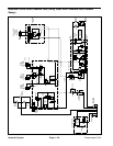
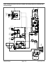
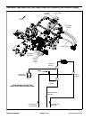
Figure 28
FRONT
S4
S3
S1R1
S2
R2
Hydraulic
System