


Greensmaster 3150 Page 5 -- 19 Electrical System
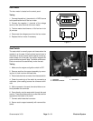
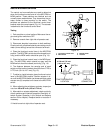
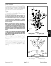
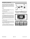
Starter Solenoid
The starter solenoidused on theGreensmaster 3150 al-
lows current flow from the battery to the engine starter
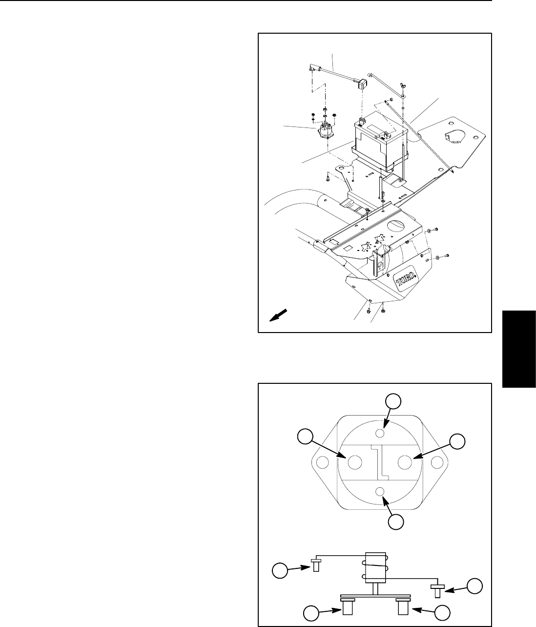
motor when energized. The starter solenoid is attached
to the r ear frame in front of the battery (Fig. 21).
Testing
1. Park machine on a level surface. Make sure the en-
gine and ignition switch are OFF.
2. Disconnect negative (black) cable from battery and
then disconnect positive (red) cable (see Battery Ser-
vice in the Service and Repairs section of this chapter).
3. Note wire locations o n starter solenoid for assemb ly
purposes. Disconnect cables and wire harness connec-
tors from solenoid.
NOTE: Prior to taking small resistance readings with a
digital multimeter, short the meter test leads together.
The meter will display a small resistance value (usually
0.5 ohms or less). This resistance is due to the internal
resistance of the meter and test leads. Subtract this val-
ue from the measured value of the component you are
testing.
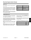
4. Apply 12 VDC directly across the solenoid coil posts.
The solenoid should click as the solenoid coil is ener-
gized. Make sure resistance across the main contact
posts is less than 1 ohm.
5. Remove voltage from solenoid coil posts. The sole-
noid should click as the solenoid coil is de--energized.
Make sure resistance across the main contact posts is
infinite ohms.
6. When testing is complete, secure cables and wire
harness connections to solenoid. Torque nuts on sole-
noid coil posts from 15 to 20 in--lb (1.7 to 2.3 N--m) and
nuts on main contact posts from 50 to 60 in--lb (5.7 to
6.8 N--m).
Figure 21
1. Starter solenoid
2. Battery
3. Positive (+) cable
4. Negative (--) cable
1
2
3
4
FRONT
Figure 22
WIRING
DIAGRAM
1. Main conta ct post
2. Solenoid coil post
2
1
2
1
2
1
2
1
Electrical
System