


Greensmaster 3150 Hydraulic SystemPage 4 -- 37
Procedure for Implement Relief Valve Pressure
Test
1. Make sure hydraulic oil is at normal operating tem-
perature by operating the machine for approximately ten
(10) minutes.
2. Park machine on a levelsurface withthe cutting units
lowered. Make sure engine is off. Make sure thehydrau-
lic tank is full.
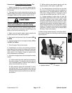
CAUTION
Before continuing further, read and become fa -
miliar with Precautions for Hydraulic Testing.
3. Measure and record charge relief valve pressure
(see Charge Relief Valve Pressure Test in this section).
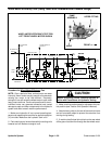
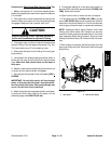
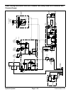
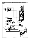
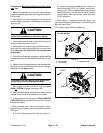
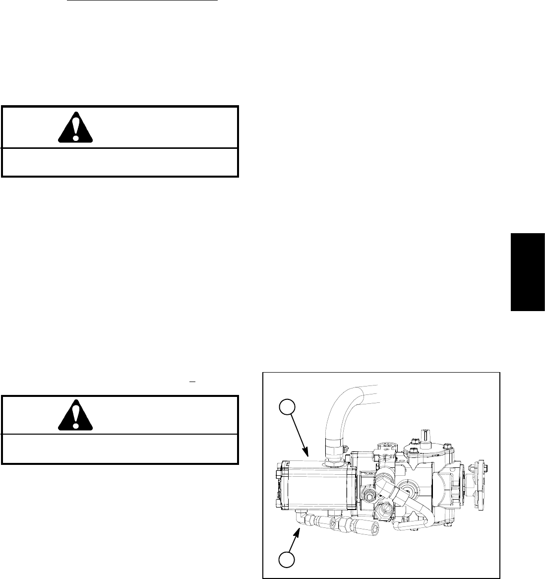
4. Thoroughly clean junction of hydraulic hose and the
hydraulic fitting in the rear gear pump section (Fig. 23).
This hose leads to port P in the steering valve.
5. Disconnect the hose from the fitting in the rear gear
pump section.
6. Install tester with p ressure gauge and flow meter in
series with the gear pump fitting an d the disconnected
hose (same connections as Gear Pump (Rear Section)
FlowTest).Make sureflow control valveon thetester
is fully open.
7. Start and run engine at full speed (2850 +
50 RPM).
CAUTION
When performing test, do not allow system pres-
sure to exceed 1400 PSI (83 bar).
8. Watch the pressure gauge on the tester and move
the joystick control to the raise position. Momentarily
hold the joystick with the cutting units fully raised caus-
ing the implement relief valve to open. Record pressure
at which the relief valve opens.
9. Release joystick to the neutral position and shut off
engine.
NOTE: The implement relief valve is in series with
charge relief valve. Charge relief pressure will affect the
implement r elief pressure.
10.Implement relief valve pressure should be 1050 to
1250 PSI (73 to 86 bar) higher than the charge relief
valve pressure (e.g. if the charge relief valve pressure
is 100 PSI (7 bar), the implement relief valve pressure
shouldbefrom1150to1350PSI(80to93bar)).
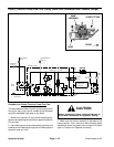
IMPORTANT: Hold steering wheel at full lock only
long enough to get a system pressure reading.
11.The implement relief valve is also activated by the
steering system. With tester still connected to gear
pump outlet, start engine and watch the pressure
gauge. Turn the steering wheel completely in one direc-
tion and hold. Relief valve should open just after rear
wheel gets to the full lock position. Relief pressure mea-
sured with the steering system should be similar to re-
sultsinstep10above.
12.If implement relief valve pressure is incorrect, in-
spect relief valve located in the steering valve (see
Steering Valve Service in the Service and Repairs sec-
tion of this Chapter). Clean relief valve or service steer-
ing valve as needed.
NOTE: Gear Pump (Rear Section) Flow Test and Low-
er Cutting Units Relief Valve Pressure can be measured
with tester positioned as described in this check (see
Gear Pump (Rear Section) Flow Test and Lower Cutting
Units Relief Valve Pressure Test in this section).
13.After testing is complete, remove tester from gear
pump fitting. Reconnect hose to the gear pump fitting.
1. Gear pump 2. Rear section fitting
Figure 23
1
2
Hydraulic
System