


Greensmaster 3150 Hydraulic SystemPage 4 -- 95
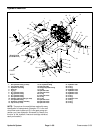
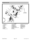
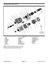
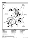
Removal (Fig. 70)
1. Before removing any parts from the hydraulic sys-
tem, park the machine on a level surface, engage the
parking brake, lower the cutting units and stop the en-
gine.
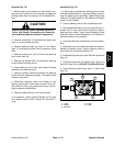
CAUTION
Before continuing further, read and become fa -
miliar with General Precautions for Removing
and Installing Hydraulic System Components.
2. Remove screw (item 10) and steering wheel cover
(item 11) from the steering wheel.
3. Remove steering wheel nut (item 9), flat washer
(item 15) and steering wheel from the steerin g valve
shaft.
4. Remove screws (item 14) and remove the steering
valve cover (item 26).
5. Remove cap screws (item 12) that secure steering
control v alve to steering mount.
6. Lower steering control valve (with hydraulic hoses
attached) from steering mount.
7. Label all hydraulic hoses connected to the steering
control valve for assembly purposes. Thoroughly clean
hydraulic hose ends.
8. Disconnect hydraulic hoses from fittings on the
steering control valve. Allow hoses to drain into a suit-
able container. Cap or plug hoses and control valve fit-
tings to prevent contamination.
9. Remove steering control valve from machine.
10.If necessary, remove hydraulic fittings and O--rings
from steering control valve. Discard all removed O--
rings.
Installation (Fig. 70)
1. If fittings were removed from steering control valve,
lubricate and place new O--rings onto fittings. Install fit-
tings into steering valve openings. Tighten fittings (see
Hydraulic Fitting Installation in the G eneral Information
section of this chapter).
2. Position steering control valve to steering mount.
3. Using labels placed during control valve removal, lu-
bricate new O--rings and connect hydraulic hoses t o
steering control valve. Tighten hose connections (see
Hydraulic Hose and Tube Installation in the General In-
formation section of this chapter).
4. Install any cable ties removed from the hose assem-
blies.
5. Slide steering control valve (with hydraulic hoses at-
tached) to steering mount. Secure steering valve to
mount with four (4) cap screws (item 12).
6. Install steering valve cover (item 26) with cap screws
(item 14).
7. Install steering wheel, flat washer (item 15) an d nut
(item 9). Torque nut from 20 to 26 ft--lb (28 to 35 N--m).
8. Secure steering wheel cover (item 11) with screw
(item 10).
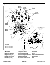
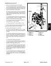
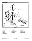
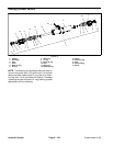
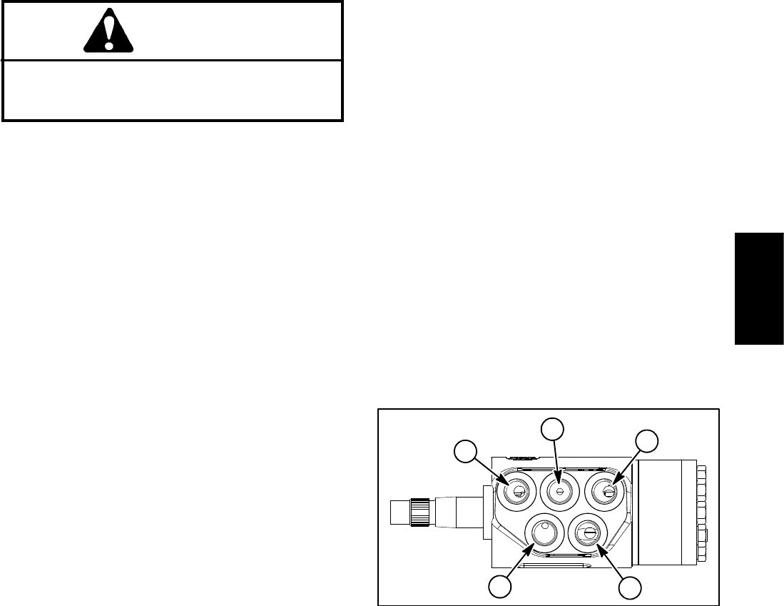
1. T port
2. R port
3. E/Ls port
4. P port
5. L port
Figure 71
2
1
3
4
5
Hydraulic
System