Greensmaster 3150 Hydraulic SystemPage 4 -- 103
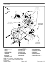
Removal (Fig. 76)
1. Before removing any parts from the hydraulic sys-
tem, park machine on a level surface, set brake, lower
cutting units and stop engine.
CAUTION
Before continuing further, read and become fa -
miliar with General Precautions for Removing
and Installing Hydraulic System Components.
2. Place a clean container, large enough to collect 2
gallons (7.6 liters), under the hydraulic pump assembly
to collect hydraulic oil.
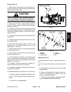
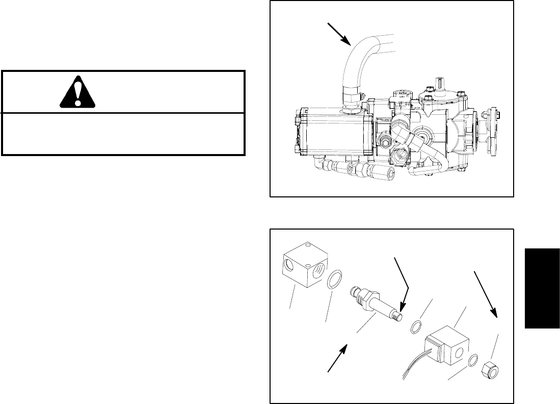
3. Clamp pump inlet hose to control drainage. Remove
inlet hose from gear pump (Fig. 77). Release clamp from
hose and drain about 2 gallons (7.6 liters) from the hy-
draulic reservoir.
4. Clamp pump inlet hose to prevent draining additional
hydraulic oil.
5. Unplug leak detector solenoid harness from the ma-
chinewireharness.
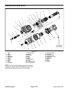
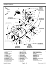
6. Remove four (4) cap screws (items 14 and 17), flat
washers (item 13), neoprene washers (item 12) and
spacers (items 11 and 18).
7. Carefully position carbon canister and bracket away
from leak detector tank.
8. Loosen either hose clamp (item 9) and disconnect
overflow hose (item 25).
9. Lift leak detector tank slightly, loosen hose clamp
(item 1) and disconnect valve hose (item 10) at barb fit-
ting (item 31) on solenoid valve assembly. Remove leak
detector tank assembly.
10.If necessary, remove solenoid valve assembly, fit-
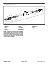
tings and hoses using Figure 76 as a guide.
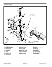
11.If needed, disassemble solenoid valve manifold us-
ingFigure78asaguide.
12.Inspect leak detector components for the following:
A. Leaking, cracked or damaged leak detector tank.
B. Worn or leaking hydraulic hoses. Replace if nec-
essary.
C. Visibly worn or damaged parts.
Figure 77
PUMP INLET HOSE
1. Manifold
2. Valve seal
3. Solenoid valve
4. O--ring
5. Solenoid coil
6. Nut
Figure 78
1
4
2
3
5
6
4
10 in--lb
(1.1 N--m)
35 ft--lb
(47 N--m)
Loctite #242
Installation (Fig. 76)
1. During assembly, coat all O--rings with clean hydrau-
lic oil.
2. If removed, assemble solenoid valve manifold (Fig
78):
A. When installing cartridge valve, torque valve 35
f t -- l b ( 4 7 N -- m ) .
B. When installing solenoid coil, apply a drop of Loc-
tite #242 (or equivalent) to threads of valve and
torque nut 10 in--lb (1.1 N--m).
C. If fittings were removed from manifold, torque fit-
tings from 40 to 50 ft--lb (55 to 67 N--m).
Hydraulic
System


