


Greensmaster 3150Groomer Page 8 -- 8
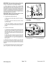
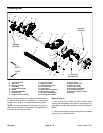
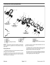
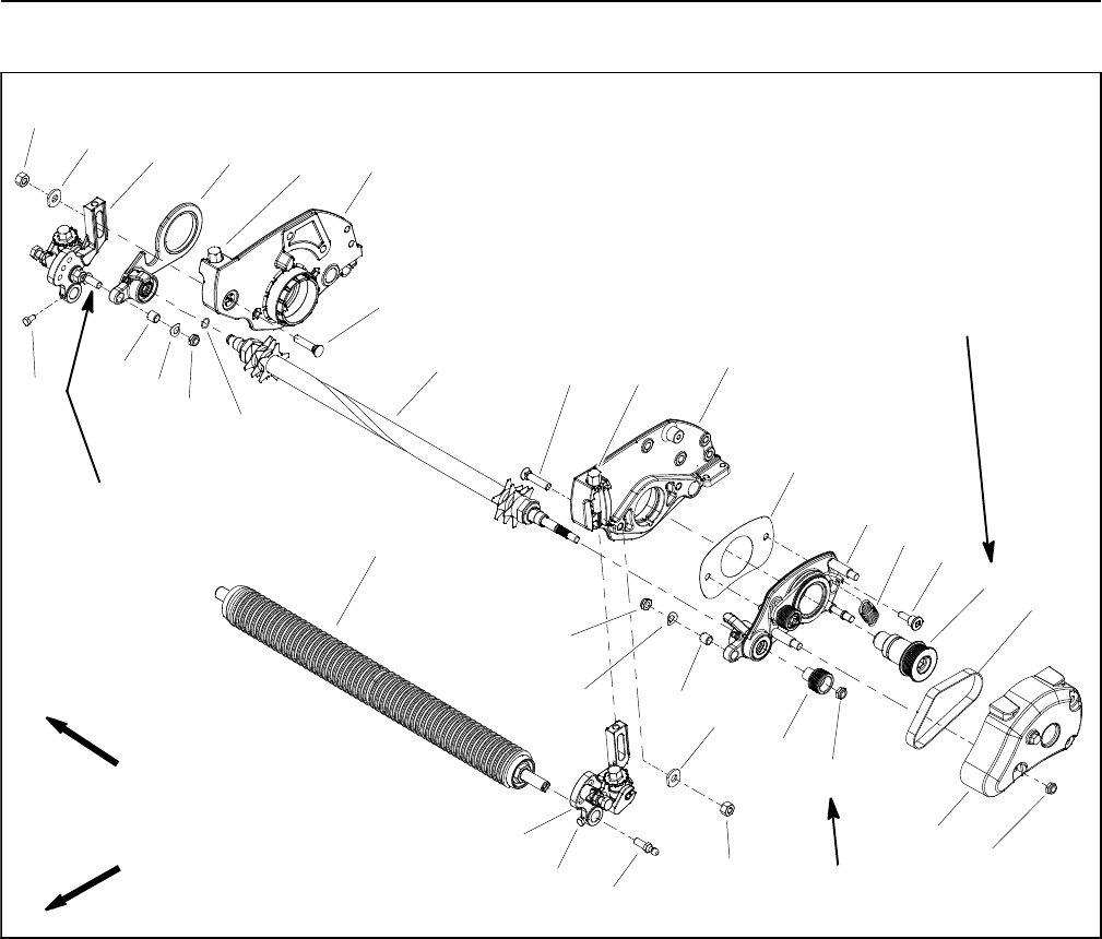
Grooming Reel
Figure 4
1. Lock nut (4 used)
2. Drive cover
3. Groomer drive belt
4. Drive pulley
5. Shoulder bolt (2 used)
6. Spring
7. Drive plate assembly
8. Groomer shim
9. RH groomer arm assembly
10. Cap screw (2 used)
11. Bushing (2 used)
12. Spring washer (2 used)
13. Lock nut (2 used)
14. Support plate
15. LH groomer arm assembly
16. HOC washer (2 used)
17. RH cutting unit sideplate
18. LH cutting unit sideplate
19. Driven pulley
20. HOC screw (2 used)
21. HOC nut (2 used)
22. Plow bolt (2 used)
23. Grooming reel assembly
24. Front roller assembly
25. Ball stud (2 used per roller)
26. O--ring
Antiseize
Lubricant
100 ft--lb
(135 N--m)
17 to 21 ft--lb
(24to28N--m)
FRONT
RIGHT
17
1
2
3
4
5
7
8
9
10
11
12
13
14
15
16
18
19
1
13
12
11
16
6
21
21
22
22
23
24
25
20
20
26
10
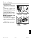
Remove the grooming reel to replace individual blades,
to replace worn groomer components, to reverse the
blades on the shaft or to replace t he grooming shaft.
NOTE: The drive assembly for the grooming reel is lo-
cated on the left side of the cutting unit (opposite from
the hydraulic cutting reel motor).
Removal (Fig. 4)
1. Park machine on a clean and level surface, lower
cutting units completely to the ground, stop engine, en-
gage parking brake and remove key from the ignition
switch.
2. Remove the cutting unit from the machine and place
cutting unit on a flat work area.