


Greensmaster 3150
DPA Cutting Units
Page 7 -- 21
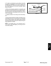
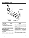
Reel Assembly Removal (Fig. 21)
CAUTION
Contact with the reel, bedknife or other c utting
unit parts can result in personal injury. Use
heavy gloves when removing the cutting reel.
1. Position machine on a clean and level surface, lower
cutting units, stop engine, engage parking brake and re-
move key from the ignition switch.
2. Remove the cutting unit from the machine and place
cuttingunitonaflatworkarea.
3. If cutting unit is equipped with an optional groomer or
rear roller brush, remove drive components for those
options from cutting unit. See Service and Repairs sec-
tion of Chapter 8 -- Groomer for information on groomer.
See Rear Roller Brush in this section for information on
rear roller brush.
4. Remove two (2) cap screws and nuts that secure
weight (item 10) to the LH side plate. Remove weight
from the cutting unit. Remove and discard O--ring from
weight.
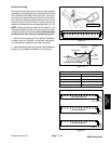
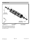
NOTE: The reel nut on the left end of the cutting reel
has a black finish and hasLH threads.The leftend of the
cutting reel shaft is identified with a groove that is just in-
side of the reel spider (Fig. 22).
5. If bearings or seals are to be removed from cutting
reel, put a block of wood between the cutting reel blades
to prevent the reel from rotating. Loosen reel nuts to al-
low easier removal after reel assembly is removed from
cutting unit (Fig. 22).
6. Remove the bedbar pivot bolt and washers from the
LH side plate. Note location of plastic and steel washers
for assembly purposes (see Bedbar Removal in this
section).
7. Loosen fasteners that secure front and rear rollers to
LH side plate (see Front Roller Removal and Rear Roller
Removal in this section).
8. Support cutting reel to prevent it from shifting or fal-
ling.
9. Remove shoulder bolts (item 4)and flange nuts (item
5) that secure the LH side plate to the cutting unit cross-
member. Remove the LH side plate from the reel shaft,
rollers, bedbar and cutting unit crossmember.
10.Carefully slide the cutting reel assembly (with
flocked seals, reel bearings and reel nuts) from the RH
side plate.
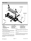
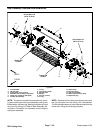
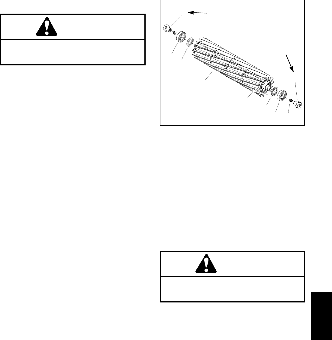
1. Cutting reel
2. Flocked seal (2 used)
3. Bearing (2 used)
4. Plug (2 used)
5. Bearing lock screw
6. Reel nut (LH threads)
7. Reel groove location
Figure 22
1
2
3
4
5
3
2
7
6
(Right Hand Threads)
90 to 110 ft--lb
(123 to 149 N--m)
90 to 110 ft--lb
(123 to 149 N--m)
(Left Hand Threads)
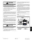
Reel Assembly Installation (Fig. 21)
1. Thoroughly clean side plates and other cutting unit
components. Inspect side plates for wear or damage
and replace components if needed.
2. Make sure that flocked seals, reel bearings and reel
nuts are properly positioned on cutting reel (see Reel
Assembly Service in this section). Apply thin coat of
grease to outside of bearings on cutting reel to ease reel
installation.
CAUTION
Contact with the reel, bedknife or other cutting
unit parts can result in personal injury. Use
heavy gloves when installing the cutting reel.
3. Position the cutting unit on a flat work area. The roll-
ers, bedbar and cutting unit crossmember should be at-
tached to RH side plate.
4. Carefully slide the cutting reel assembly (with
flocked seals, reel bearings and reel nuts) into the RH
side plate. Make sure that bearing is fully seated into
side plate.
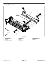
5. Place flat wire spring (item 14) into bearing bore of
LH side plate. Carefully slide the LH side plate onto the
cutting reel assembly, front roller and rear roller. Make
sure that side plate is fully seat ed onto bearing on reel
shaft.
DPA Cutting
Units