


Greensmaster 3150Page 6 -- 4Chassis
Service and Repairs
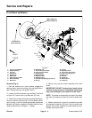
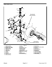
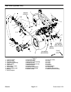
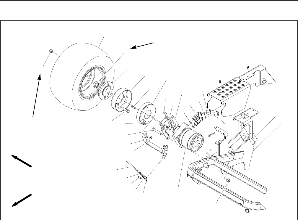
Front Wheel and Brakes
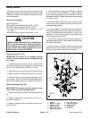
Figure 2
1. Lug nut (4 per wheel)
2. Wheel a ssembly
3. Lock nut
4. Brake lever
5. Brake drum
6. Wheel hub
7. Drive stud (4 per hub)
8. Brake assembly
9. Brake cam
10. Retaining r ing
11. Cap screw (4 per brake)
12. Lock nut (4 per brake)
13. Woodruff key
14. Brake bracket
15. Hydraulic hose
16. Hydraulic hose
17. 45
o
Hydraulic fitting (2 per motor)
18. O--ring
19. O--ring
20. Hydraulic motor
21. Cap screw (4 per motor)
22. Lock nut (4 per motor)
23. Brake rod
24. Jam nut
25. Clevis pin
26. Swivel clevis
27. Cotter pin
FRONT
RIGHT
250 to 400 ft--lb
(339 to 542 N--m)
70 to 90 ft--lb
(95 to122 N--m)
2
3
6
8
9
10
11
13
1
5
7
12
14
15
16
17
18
19
20
4
21
22
23
24
25
26
27
Removal (Fig. 2)
1. Park the machine on a level surface, engage the
parking brake, lower the cutting units and stop the en-
gine. Remove key from the ignition switch.
2. Loosen, but do not remove, lug nuts (item 1) and lock
nut (item 3). Loosen lock nut at least two (2) turns.
3. Chock front and rear of wheels not being lifted to pre-
vent the machine from moving. Lift front wheel off the
ground using a jack and place appropriate jackstands
beneath the frame to support the raised machine (see
Jacking Instructions in Chapter 1 -- Safety).
4. Remove lug nuts and wheel a ssembly from drive
studs.
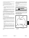
IMPORTANT: DO NOT hit wheel hub (item 6) with a
hammer during removal or installation. Hammering
may cause damage to the hydraulic wheel motor.
NOTE: The brake drum assembly consists of the wheel
hub (item 6), brake drum (item 5) and drive studs (item
7).
5. Make sure that lock nut (item 3) on wheel motor shaft
is loosened at least two (2) tur ns. Use hub puller (see
Special Tools in this chapter) to loosen brake drum as-
sembly from wheel motor.