


Greensmaster 3150
DPA Cutting Units
Page 7 -- 30
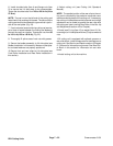
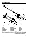
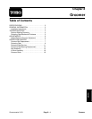
Roller Service
1. Wiehle roller
2. Smooth roller
3. Roller shaft
4. Ball bearing
5. Seal
6. V--ring
7. Bearing lock nut
Figure 29
7
6
5
4
2
1
3
4
5
6
7
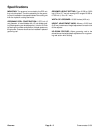
25 to 30 ft--lb
(34to41N--m)
25 to 30 ft--lb
(34to41N--m)
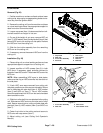
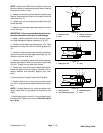
Disassembly
1. To hold roller shaft for bearing lock nut removal,
install a 3/8--24 UNF2B screwinto threaded end ofroller
shaft and secure screw in place with jam nut. While re-
taining shaft, remove bearing lock nut from each end of
roller shaft.
2. Remove V--ring from each end of roller.
3. Carefully inspect seating surface and threads of
bearing lock nuts. Replace lock nut if any damage is
found.
4. Loosely secure roller assembly in bench vise and
lightly tap one end of roller shaft until seal and bearing
areremovedfrom roller cavity.Removesecond seal and
bearing from r oller cavity by tapping on shaft.
5. Clean bearing cavity in roller and remove any rust
with crocus cloth.
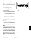
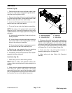
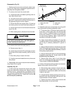
Assembly
1. Place roller shaft into roller.
NOTE: If bearing lock nuts are being replaced, use
original lock nuts for assembly purposes, if possible.
This will preserve the patch lock feature in the new lock
nuts. Use the new nuts only after new bearings and
seals have been installed.
1. Roller
2. Ball bearing
3. Seal
4. V--ring
5. Bearing lock nut
6. Roller shaft
Figure 30
3
5
4
2
1
6
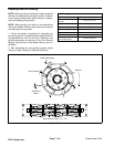
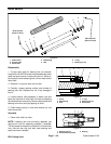
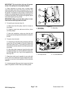
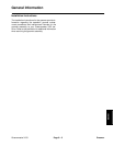
1. Bearing lock nut
2. Black assembly washer
3. Bearing
Figure 31
3
2
1