Greensmaster 3150 Page 6 -- 15 Chassis
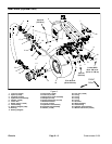
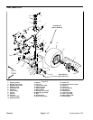
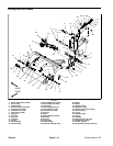
NOTE: The pull frame assemblies used on Greens-
master 3150 machines are slightly different depending
on location (right front, left front and center positions).
Service of the pull frame assembly is similar regardless
of position on the machine. The right front pull frame as-
sembly is shown in Figure 11.
Disassembly (Fig. 11)
1. Park machine on a level surface with cutting units
lowered to the ground. Make sure engine is off. Engage
parking brake.
NOTE: Depending on service that is required, it might
be easier to remove cutting unit from pull frame.
2. Remove cutting unit pull frame components from
machine as required using Figure 11 as a guide.
Assembly (Fig. 11)
1. Install all removed cutting unit pull frame compo-
nents to machine using Figure 11 as a guide.
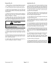
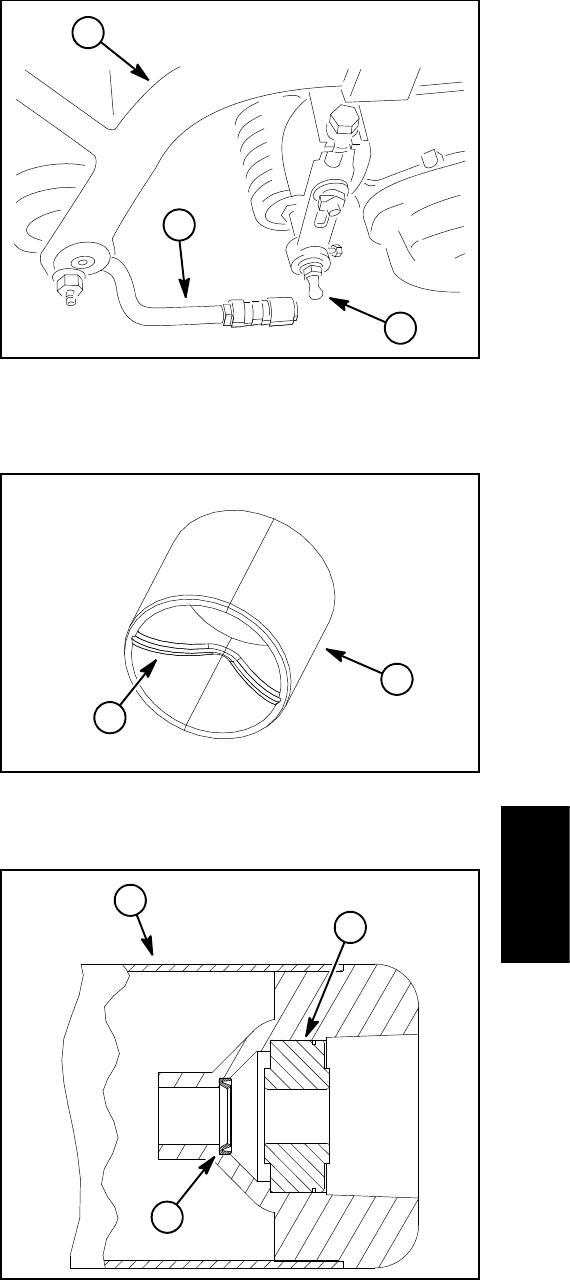
A. If bushings (item 38) in lift arm or pivot hinge are
being replaced, install new bushing so that grease
groove opening is orientated inward. The bushing
with grease groove is shown in Figure 13.
B. If pivot hinge (item 17) was removed, make sure
that side play clearance of pivot hinge is less than
0.060” (1.5 mm). Adjust clearance with shims (item
15) and thrust washers (item 16) as required.
C. If roller assembly was disassembled, install oil
seal with seal lip toward end of roller (Fig. 14). Also,
ball bearing should be installed with seal toward end
of roller.
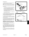
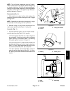
1. Pull frame
2. Pull arm
3. Cutting unit ball stud
Figure 12
2
1
3
1. Bushing 2. Grease groove
Figure 13
1
2
1. Roller
2. Oil seal
3. Ball bearing
Figure 14
2
1
3
Chassis


