


Greensmaster 3150 Page 5 -- 11 Electrical System
Electrical System Quick Checks
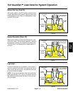
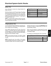
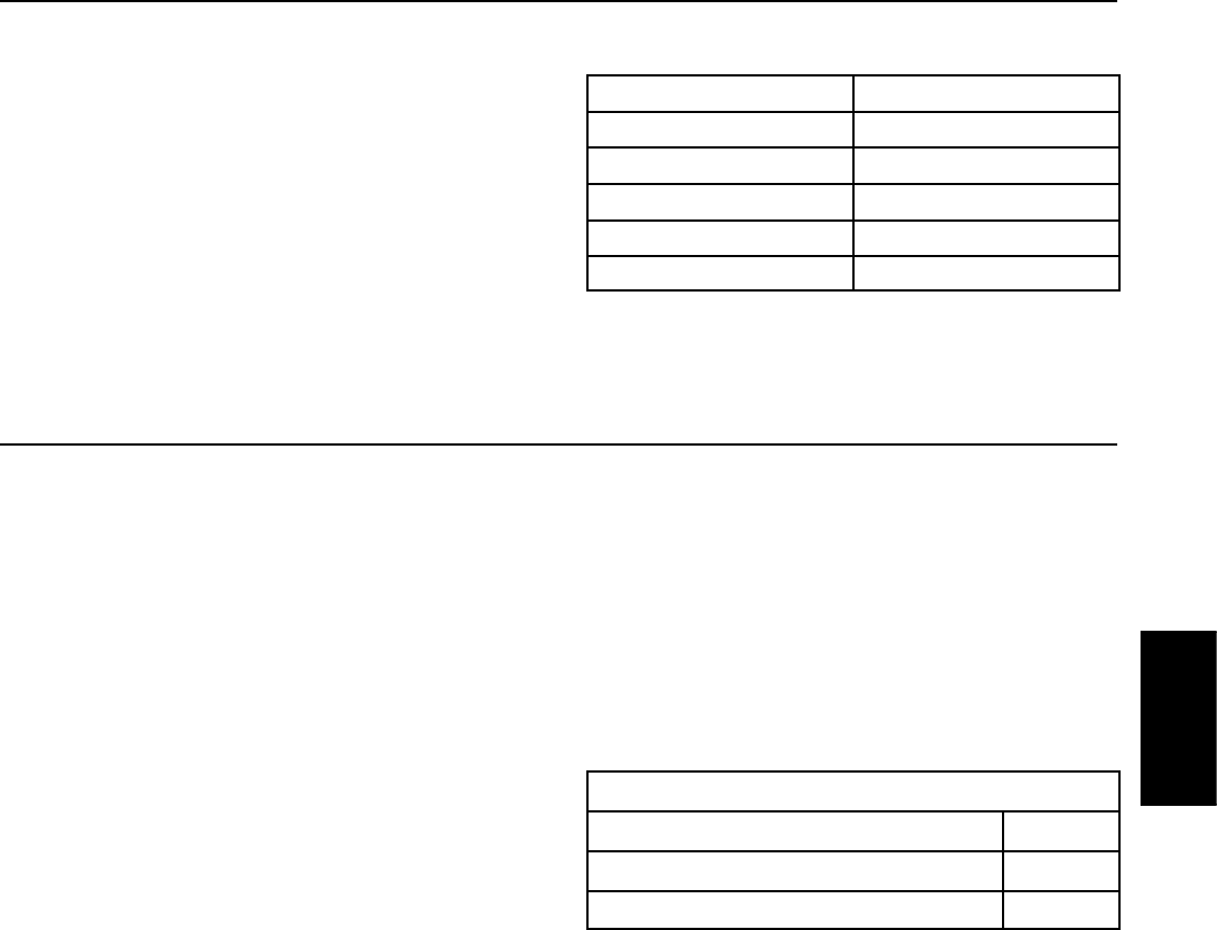
Battery Test
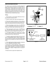
Use a multimeter to measure the voltage between the
battery terminals.
Set the multimeter to the DC volts setting. The battery
should be at a temperature of 60
o
to 100
o
F(16
o
to 38
o
C). The ignition key should be off and all a ccessories
turned off. Connect the positive (+) meter lead to the
positive battery post and the negative (--) meter lead to
the negative battery post.
NOTE: This test provides a relative condition of the bat-
tery. Load testing of the battery will provide additional
and more accurate information.
Voltage Measured
Battery Charge Level
12.68 V (or higher) Fully charged (100%)
12.45 V 75% charged
12.24 V 50% charged
12.06 V 25% charged
11.89 V 0% charged
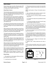
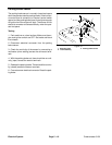
Charging System Test
This is a simple test used to determine if a charging sys-
tem is functioning. It will tell you if the charging system
has an output, but not its capacity.
Use a digital multimeter set to DC v olts. Connect the
positive (+) multimeter lead to the positive battery post
and the negative (--) multimeter lead to the negative bat-
tery post. Keep the test leads connected to the battery
posts and record the battery voltage.
NOTE: Upon starting the engine, the battery voltage
will drop and then should increase once the engine is
running.
NOTE: Depending upon the condition of the battery
charge and battery temperature, the battery voltage will
increase at different rates as the battery charges.
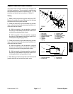
Start the engine and run at high idle (2850 RPM). Allow
the battery to charge for at least three (3) minutes. Re-
cord the battery voltage.
After running the engine for at least three (3) minutes,
battery voltage should be at least 0.50 volt higher than
initial battery voltage.
An example of a charging system that is functioning:
At least 0.50 volt over initial battery voltage.
Initial Battery Voltage = 12.30 v
Battery Voltage after 3 Minute Charge = 12.95 v
Difference =+0.65v
Electrical
System