Greensmaster 3150 Page 3 -- 7 Engine
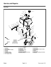
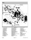
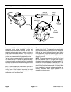
Engine Removal (Fig. 2)
1. Park machine on a level surface, lower cutting units,
stop engine, engage parking brake and remove key
from the ignition switch.
2. Disconnect negative (--) battery cable from battery.
CAUTION
The muffler and exhaust manifold may be hot.
Avoid possible burns, allow exhaust system to
cool before working on the engine.
DANGER
Gasoline is flammable. Use cautionwhen storing
or handling it. Do not smoke while filling the fuel
tank. Do not fill fuel tank while engine is running
or in an enclosed area. Always fill fuel tank out-
side and wipe up any spilled fuel before starting
the engine. Store fuel in a clean, safety-- ap-
proved container and keep the cap in place. Use
gasoline for the engine only; not for any other
purpose.
3. Close fuel shut--off valve on fuel tank.
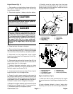
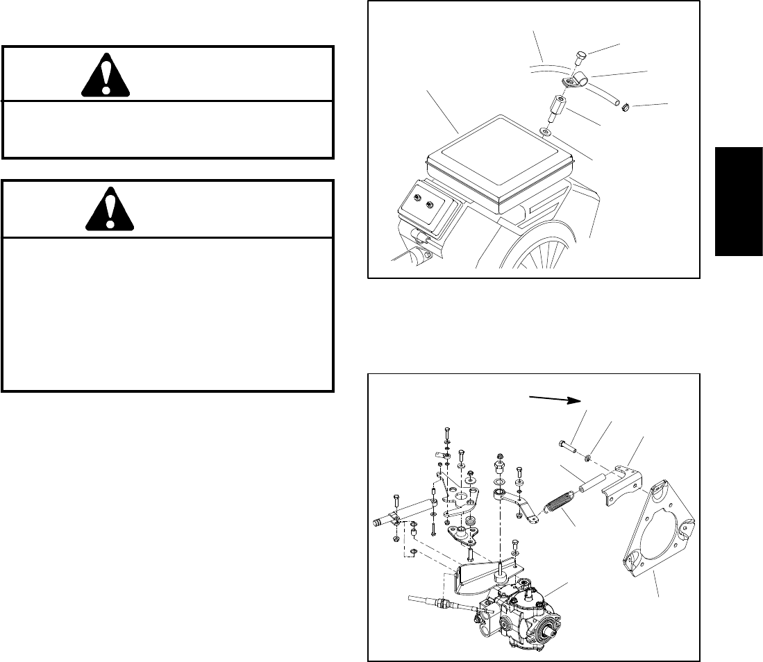
4. Remove the fuel hose support clamp and disconnect
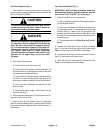
fuelhose at the fuel pump (Fig. 3). Drainanyfueltrapped
in the fuel filter and fuel hose into a suitable container.
5. Disconnect the fuel evaporative control system
hoses from engine (see Fuel Evaporative Control Sys-
tem in this section).
6. Disconnect the engine wiring harness (item 29), the
choke control cable, the throttle control cable and the
ground wires (item 11) at the engine.
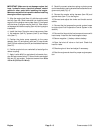
7. Carefully disconnect extension spring on piston
pump control assembly from spring bracket that is at-
tached to engine mount plate (Fig. 4).
8. Loosen the two (2) set screws (item 47) securing the
engine hub (item 41) to the engine shaft.
9. Support the piston pump assembly and remove the
two (2) cap screws (item 53), lock washers (item 52) and
hardened washers (item 51) securing the pump to the
pump adapter (item 19). Do Not disconnect the hydrau-
lic hoses or neutral control linkage from the pump.
10.Support the engine assembly and remove the three
(3) e ngine mount flange nuts (item 7), cap screws (item
1), flat washers (item 2) and spacers (item 3).
11.Carefully move the engine away from the piston
pump until the crankshaft clears the engine hub. Re-
move the engine from the machine. Locate and retrieve
key (item 48) from crankshaft.
Figure 3
1. Engine assembly
2. Fuel supply hose
3. Cap screw
4. Support clamp
5. Hose clamp
6. Spacer screw
7. Washer
2
3
6
1
5
7
4
Figure 4
1. Engine mount plate
2. Spring bracket
3. Lock washer (2 used)
4. Cap screw (2 used)
5. Dampener hose
6. Extension spring
7. Piston pump assembly
2
3
6
1
5
7
4
25 to 38 ft--lb
(34to51N--m)
Engine Installation (Fig. 2)
1. Make sure that all parts removed from the engine
during maintenance or rebuilding are installed to the en-
gine.
2. Apply antiseize lubric ant to bore of engine hub.
Place key (item 48) into slot on the engine crankshaft.
Engine


