


Greensmaster 3150Page 3 -- 10Engine
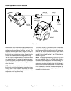
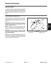
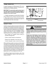
Fuel Evaporative Control System
Figure 5
CHECK
VALVE
CHECK
VALVE
FRESH AIR
FILTER
CARBON
CANNISTER
FUEL
TANK
ENGINE
TO INTAKE
MANIFOLD
TO AIR
CLEANER
Greensmaster 3150 machines are equipped with a fuel
evaporative control system designed to collect and
store evaporative em issions from the fuel tank. The
evaporate control system uses a carbon cannister to
collect these evaporative emissions. Fuel vapors from
the fuel tank are vented to the canister. Vapors from the
canister are consumed when the engine is running.
The fuel tank on Greensmaster 3150 machines uses a
non--vented fuel cap. To connect the tank to the evapo-
rative control s ystem, afuel tank vent fitting is positioned
in the top of the tank that allows tank venting through the
carbon cannister.
NOTE: If there is restriction in the carbon cannister or
the fuel tank vent fitting, the fuel tank may distort due to
venting issues. If the fuel tank returns to it’s normal
shape when the fuel cap is removed, restriction in the
evaporative control system is likely.
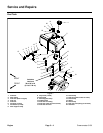
The carbon canister is mounted on the hydraulic leak
detector tank (Fig. 6). The evaporative system includes
two (2) connections to the engine: one to the intake man-
ifold and the second to the air cleaner base. Venting
hose assemblies (purge hose assembly and t--hose as-
sembly) include check valves in two (2) locations as
showninFigure5.
NOTE: The purge hose assembly (item 5 in Fig. 6) and
teehoseassembly(item10inFig.6)bothincludea
check valve as a component of the hose assembly. The
check valve is not available as a separate part. To en-
sure proper operation of check valves, do not attempt to
remove them from the hose assembly. If either of these
hose assemblies is removed, make sure that they are
correctly installed to ensure proper operation of the
evaporative control system.