


Greensmaster 3150 Hydraulic SystemPage 4 -- 57
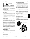
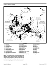
6. Support the pump assembly and gently tap the
pump housing with a soft face hammer to loosen the
pump sections. Be careful to not drop parts or disen-
gage gear mesh.
IMPORTANT: Mark the relative po sitions of the gear
teeth and the thrust plates so they can be as-
sembled in the same position. Do not touch thegear
surfaces as residue on hands may be corrosive to
gear finish.
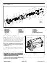
7. Remove the thrust plates and seals from each pump
section. Before removing each gear set, apply marking
dye to mating teeth to retain ”timing”. Pump efficiency
may be affected if the teeth are not installed in the same
position during assembly. Kee p the parts for each pump
section together; do not mix parts between sections.
8. Clean all parts. Check all components for burrs,
scoring, nicks and other damage.
9. Replace the entire pump assembly if any pump com-
ponents are excessively worn or scored.
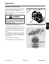
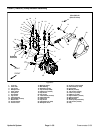
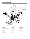
Gear Pump Assembly (Fig. 38)
1. Apply clean hydraulic oil to all parts before assem-
bling.
NOTE: Pressure and back--up seals fit in grooves ma-
chinedinto thrust plates. Body O--rings fit in groovesma-
chined in housing.
2. Assemble pump sections starting at front cover end.
Apply grease or petroleum jelly to new section seals to
hold them in position during gear pump assembly.
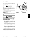
3. After pump has been assembled, tighten socket
head screws by hand. Rotate the drive shaft to check for
binding. Protect the shaft if using a pliers to rotate shaft.
4. Tighten the socket head screws evenly in a crossing
patterntoatorqueof33 ft--lb (45 N--m).
Hydraulic
System