


Greensmaster 3150 Hydraulic SystemPage 4 -- 55
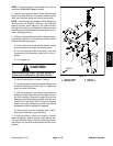
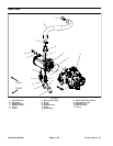
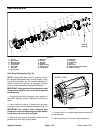
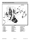
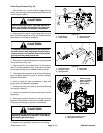
Removal (Fig. 36)
CAUTION
Before continuing further, read and become fa -
miliar with General Precautions for Removing
and Installing Hydraulic System Components.
1. Before removing any parts from the hydraulic sys-
tem, park machine on a level surface, engage parking
brake, lower cutting units and stop engine. Remove key
from the ignition switch.
2. Label all hose connections for a ssembly purposes.
3. Clamp pump inlet hose to prevent draining the hy-
draulic reservoir.
4. Loosen hose clamp and remove pump inlet hose
from the gear pump. Allow clamped hose to drain into a
suitable container.
5. Disconnect hydraulic hoses from fittings on bottom
of the gear pump. Allow hoses to drain into a suitable
container. Plug hoses to prevent contamination.
IMPORTANT: Note position of hydraulic fittings for
assembly purposes.
6. Mark hydraulic fitting orientation to allow correct as-
sembly. Remove hydraulic fittings and O--rings from
gear pump.
7. Support gear pump to prevent it from shifting. Sepa-
rate gear pump from the piston pump by removing both
socket head screws and flat washers. Remove O--ring
from between the gear pump and piston pump.
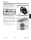
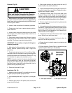
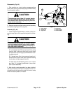
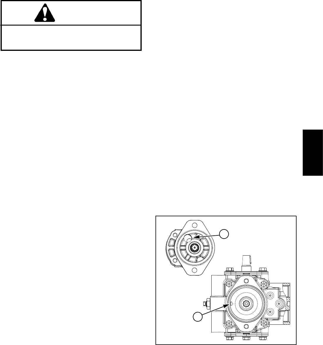
NOTE: A case drain exists in the piston (traction) pump
and a suction port is near the input shaft of the gear
pump (Fig. 37). When the gear pump is r emoved from
the piston pump, plug piston pump case drain hole to
prevent draining the piston pump.
8. Discard all removed O--rings.
Installation (Fig. 36)
1. Make sure mounting and O--ring sealing surfaces on
the gear pump and piston pump are clean.
2. Lubricateand place newO--ring (item 11) onthe gear
pump.
3. Position gear pump to the piston pump so that the
pump inlet is facing up.
4. Secure gear pump to the piston pump with two (2)
socket h ead screws and flat washers.
5. Inspect threads and sealing surfaces of hydraulic fit-
tings and hydraulic hose connectors. Replace any dam-
aged or worn fittings or hoses.
6. Lubricate and place new O--rings onto gear pump
hydraulic fittings. Install fittings into pump openings
making sure that fitting orientation is as noted during re-
moval. Tighten fittings (see Hydraulic Fitting Installation
in the General Information section of this chapter).
7. Remove plugs that were placed during disassembly
from hydraulic hoses.
8. Using labels placed duringgear pump removal,lubri-
cate new O--rings and connect hydraulic hoses to lower
gear pump fittings. Tighten hose connections (see Hy-
draulic Hose and Tube Installation in the General Infor-
mation section of this chapter).
9. Install pump inlet hose to the hose connector ongear
pump.Securehosewithhoseclamp.
10.Remove clamp from pump inlet hose to allow hy-
draulic oil flow to the gear pump.
11.Check oil level in hydraulic reservoir and add correct
oil if necessary.
12.Follow Hydraulic System Start--up procedures (see
Hydraulic System Start--up in this section).
1. Piston pump case drain 2. Gear pump suction port
Figure 37
2
1
Remove plugs
before installing
gear pump to
piston pump
Hydraulic
System