Greensmaster 3150 Hydraulic SystemPage 4 -- 89
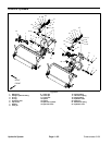
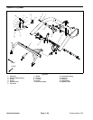
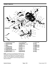
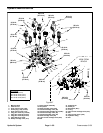
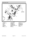
Removal (Fig. 66)
1. Before removing any parts from the hydraulic sys-
tem, park machine on a level surface, engage parking
brake, lower cutting units and stop the engine.
CAUTION
Before continuing further, read and become fa -
miliar with General Precautions for Removing
and Installing Hydraulic System Components.
2. Label all hydraulic connections and electrical con-
nections for assembly.
3. Disconnect wire harness connectors from manifold
solenoid coils and backlap switch.
IMPORTANT: Before disconnecting any hydraulic
lines from the hydraulic fittings, makesureeachline
is labeled to ensure it is reconnected to the correct
manifold fitting/port.
4. Disconnect hose and tube assemblies and remove
their respective O--rings from the hydraulic fittings. Al-
low hoses and tubes to drain into a suitable container.
5. Remove two (2) cap screws (item 13) from the hy-
draulic manifold. Remove manifold assembly from the
machine.
IMPORTANT: Before disconnecting any hydraulic
fittings from the hydraulic manifold block, make
sure the position of each fitting is observed and re-
corded to ensure proper installation.
IMPORTANT: A flow control orifice is located be-
neath the fitting in manifold port L1A. If this fitting
is removed from the manifold, make sure to remove
orifice and label its position for assembly purposes.
When installing the orifice in the manifold, make
sure that the orifice is flat in the base of the port.
Manifold dama ge is possible if the orifice is cocked
in the port.
6. If necessary, remove hydraulic fittings and O--rings
from the manifold.
Installation (Fig. 66)
1. Install hydraulic fittings an d their respective O--rings
to the manifold assembly and orient to position recorded
during removal. Torque fittings to the values identified in
Figure 66.
2. Position manifold assembly to the support frame.
Secure assembly to the frame with two (2) cap screws
(item 13).
3. Using labels placed during disassembly, connect hy-
draulic hoses and tubes and their respective O--rings to
correct hydraulic fittings.
A. When installing hydraulic tube (item 15) to 90
o
hydraulic fitting in manifold port T, torque tube from
55 to 65 ft--lb (75 to 88 N--m).
4. Connect wire harness connectors to manifold sole-
noid coils and backlap switch.
5. Make sure that hydraulic reservoir is at correct level.
6. Start machine. Run machine at idle for several min-
utes to circulate hydraulic fluid and remove any air
trapped in the system. Stop machine and recheck hy-
draulic reservoir level.
Hydraulic
System


