


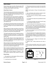
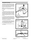
Greensmaster 3150Page 5 -- 22Electrical System
Diodes
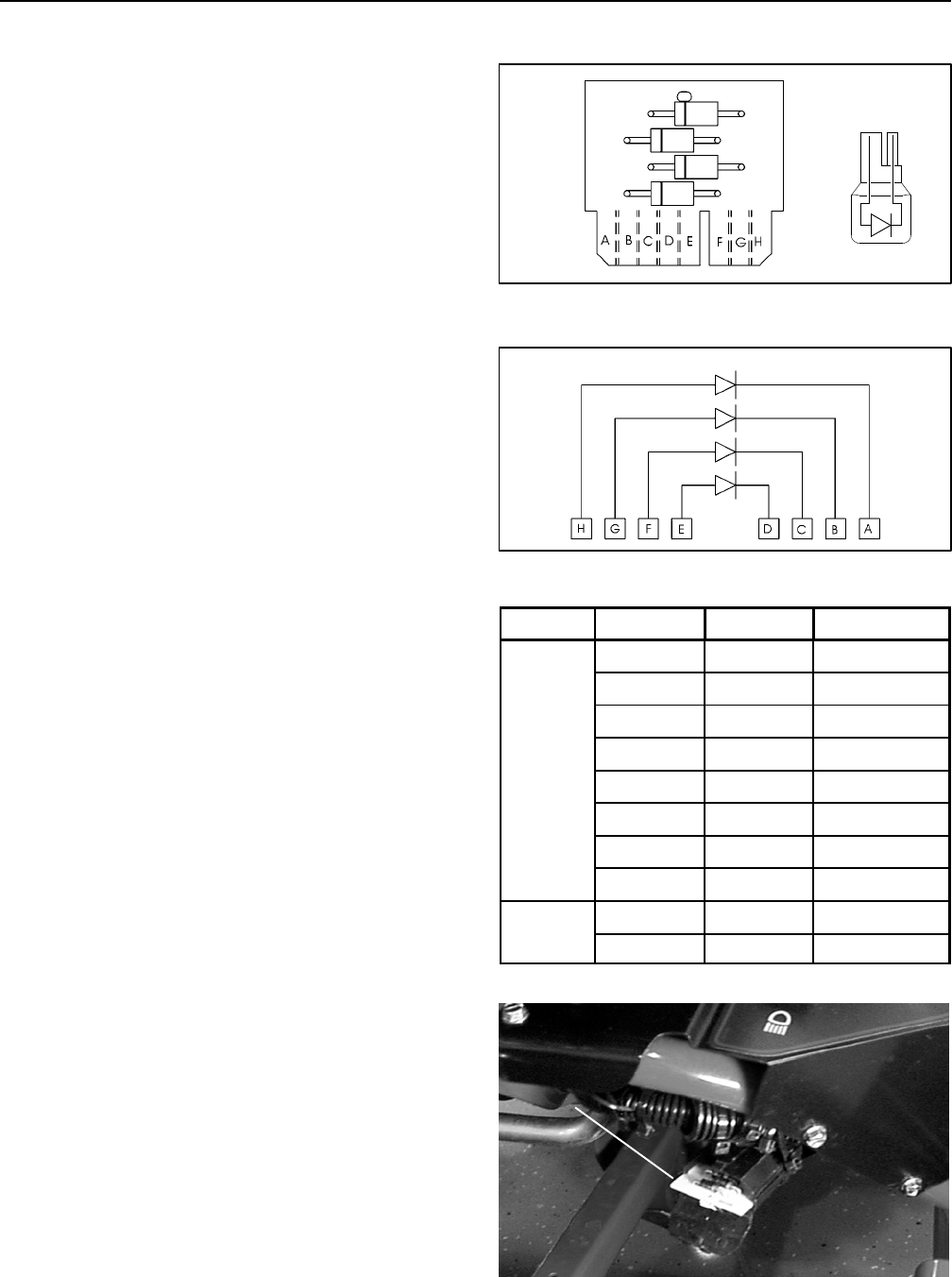
The main wiring harness contains six (6) diodes. Diodes
D2 and D3 are connected to the harness at separate
locations. Diodes D1--A, D1--B, D1--C and D1--D are
connected to the main harness by a four (4) position cir-
cuit board located near the front of the left side control
panel. The diodes are used for circuit protection from in-
ductive voltage spikes and for safety circuit logic.
Apply dielectric grease (Toro part number 107--0342) to
circuit board contacts whenever the circuit board is
installed into the wire harness.
Diode D1--A
Allows the engine to start only with the functional control
lever in NEUTRAL(neutral switch closed). Also, it allows
theenginetocontinuetorunwitheitherthefunctional
control lever in NEUTRAL (neutral switch closed) or the
operator sitting in the seat (seat switch closed).
Diode D1--B
Prevents a negative spike from damaging the neutral
switch and seat switch by allowing a ground path for the
start safety relay (K2) when it de--energizes.
Diode D1--C
Maintains current flow to the joystick relay (K3) after the
momentary lower switch of the joystick o pens.
Diode D1--D
Prevents a negative spike from damaging the mow and
backlap switches by allowing a ground path for the mow
relay (K4) when it de--energizes.
Diode D2
Thisdiodeprevents current flow to solenoidS4when so-
lenoids S2 and S3 are energized through raise relay
(K6).
Diode D3
Thisdiodeprevents current flow to solenoidS3when so-
lenoids S2 and S4 are energized through lower relay
(K5).
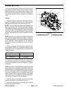
Testing
The diodes can be individually tested using a digital
multimeter (ohms setting) and the table to the right.
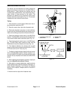
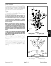
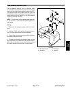
Figure 25
DIODE
CIRCUIT
BOARD
PLUG-IN
DIODE
D1--D
D1--C
D1--A
D1--B
1/A 2/B
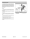
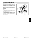
Figure 26
D1--A
D1--B
D1--C
D1--D
DIODE CIRCUIT BOARD
Type
Red (+) Black (--)
Continuity
Circuit
Board
H A
YES
A H
NO
G B
YES
B G
NO
F C
YES
C F
NO
E D
YES
D E
NO
Plug-In
1/A 2/B
YES
2/B 1/A
NO
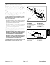
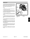
Figure 27
DIODE
CIRCUIT BOARD