


Greensmaster 3150Hydraulic System Page 4 -- 56
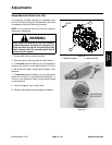
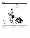
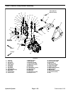
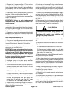
Gear Pump Service
1. O--ring
2. Front cover
3. Back--up seal
4. Pressure seal
5. Thrust plate
6. Drive shaft
7. Idler gear
8. Thrust plate
9. Dowel pin
10. O--ring
11. Housing
12. Coupler
13. Back--up seal
14. Pressure seal
15. Thrust plate
16. Drive gear
17. Idler gear
18. Thrust plate
19. O--ring
20. End cover
21. Socket head screw (4 used)
22. Washer (4 used)
Figure 38
2
3
6
8
9
10
11
13
1
5
7
12
14
15
16
17
18
19
20
4
21
22
3
4
14
13
33 ft--lb
(45 N--m)
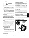
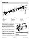
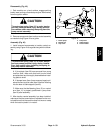
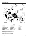
Gear Pump Disassembly (Fig. 38)
NOTE: Disassemble gear pump for cleaning, inspec-
tion and seal replacement only. Individual gears, hous-
ings and thrust plates are not available separately. If
internal components are worn or damaged, the gear
pump must be replaced as a complete assembly.
IMPORTANT: Keep gears and thrust plates for each
pump section together; do not mix parts between
pump sections.
1. Plug pump ports and thoroughly clean exterior of
pump with cleaning solvent. Make sure work area is
clean.
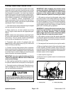
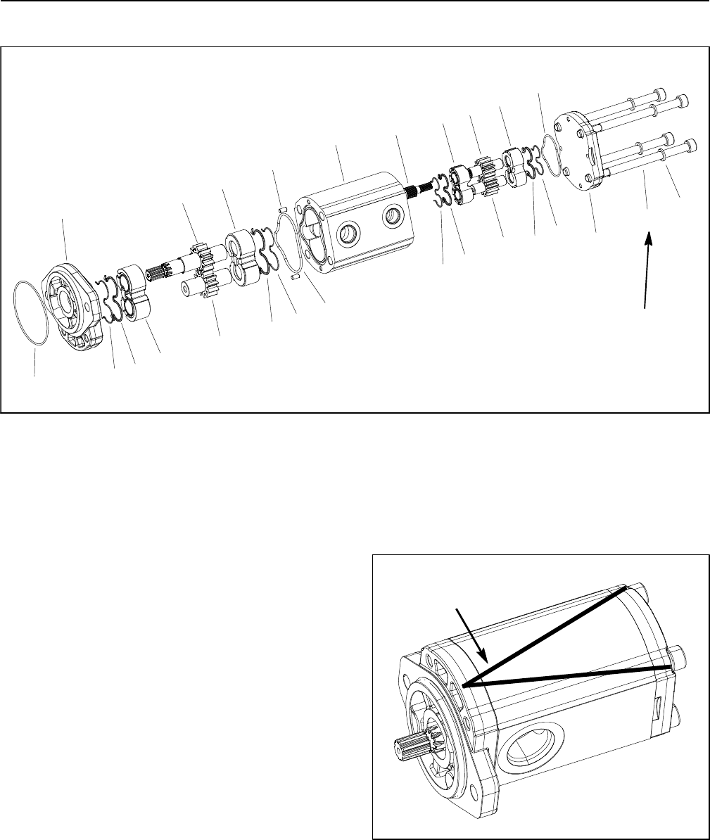
2. Useamarkertomakea“V”acrossthefrontcover,
housing and end cover for assembly purposes (Fig. 39).
IMPORTANT: Use caution when clamping gear
pump i n a vise to avoid distorting any pumpcompo-
nents. Also, use a vise with soft jaws.
3. Secure the front cover of the pump in a vise with soft
jaws with the drive shaft pointing down.
Figure 39
MARKER LINES
4. Loosen the four (4) socket head screws that secure
pump assembly.
5. Remove pump from vise and remove fasteners.