


Greensmaster 3150 Hydraulic SystemPage 4 -- 39
Procedure for Lower Cutting Units Relief Valve
(R2)
Pressure
Test
1. Make sure hydraulic oil is at normal operating tem-
perature by operating the machine for approximately ten
(10) minutes.
2. Park machine on a levelsurface withthe cutting units
lowered. Make sure engine is off. Make sure thehydrau-
lic tank is full.
CAUTION
Before continuing further, read and become fa -
miliar with Precautions for Hydraulic Testing.
3. Measure and record charge relief valve pressure
(see Charge Relief Valve Pressure Test in this section).
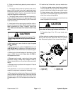
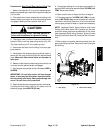
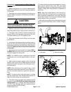
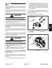
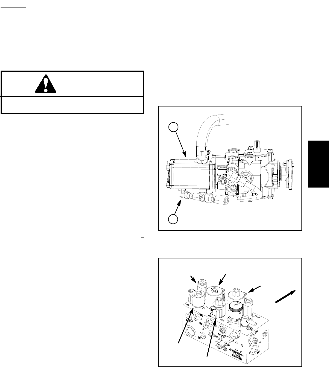
4. Thoroughly clean junction of hydraulic hose and the
hydraulic fitting in the rear gear pump section (Fig. 24).
This hose leads to port P in the steering valve.
5. Disconnect the hose from the fitting in the rear gear
pump section.
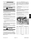
6. Install tester with p ressure gauge and flow meter in
series with the gear pump fitting an d the disconnected
hose (same connections as Gear Pump (Rear Section)
FlowTest).Make sureflow control valveon thetester
is fully open.
7. Start engine and move throttle to full speed (2850 +
50 RPM). Make sure that cutting units are fully lowered
and then engage the cutting units.
NOTE: The LOWER function is electrically timed and
automatically turns off after approximately six (6) sec-
onds.
8. Watch pressure gauge carefully while moving the
joystick control lever to the LOWER position and note
pressure that relief valve opens. Shut off engine and re-
cord test results.
NOTE: While performing this hydraulic test, if relief
pressure cannot be determined within the LOWER func-
tion six ( 6) second timeframe, repeat this test proce-
dure.
NOTE: The lower cutting units relief valve is in series
with the charge relief valve. Charge relief pressure will
affect the lower cutting units relief pressure.
9. The lower cutting units relief valve pressure should
be approximately 400 PSI (28 bar) higher than charge
relief pressure (e.g. if charge r elief valve pressure is
100 PSI (7 bar), the lower relief valve pressure should
be approximately 500 PSI (35 bar)).
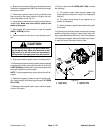
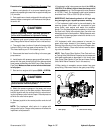
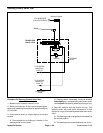
10.If lowercutting unitsrelief valve pressure isincorrect,
adjust control manifold relief valve (R2) (see Adjust
Manifold Relief Valves in the Adjustments section of this
Chapter). Retest relief valve pressure if adjustment is
performed.
NOTE: Gear Pump (Rear Section) Flow Test and Im-
plement Relief Valve Pressure can be measured with
tester positioned as described in this check (see Gear
Pump (Rear Section) Flow Test and Implement Relief
ValvePressureTestinthissection).
11.After testingis complete, disconnect tester from gear
pump and hose. Reconnect hose to hydraulic fitting on
pump.
1. Gear pump 2. Rear section fitting
Figure 24
1
2
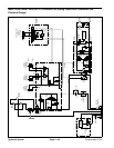
Figure 25
FRONT
S3
S1R1
S4
RELIEF
VALVE (R2)
S2
Hydraulic
System