


Greensmaster 3150 Hydraulic SystemPage 4 -- 85
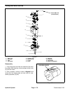
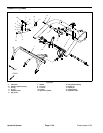
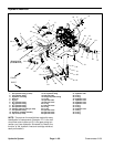
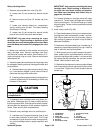
Center Lift Cylinder Removal (Fig. 63)
1. Before removing any parts from the hydraulic sys-
tem, park the machine on a level surface, engage the
parking brake, lower the cutting units and stop the en-
gine.
CAUTION
Before continuing further, read and become fa -
miliar with General Precautions for Removing
and Installing Hydraulic System Components.
2. Label all hydraulic connections for assembly pur-
poses.
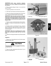
3. Disconnect hose assemblies and O--rings from the
hydraulic fittings at the lift cylinder. Allow hoses to drain
intoasuitablecontainer.
4. Support lift cylinder to prevent it from dropping.
A. Remove cap screw, washer and lock nut from the
pivot pin (item 8). Pull pivot pin from the frame and lift
cylinder.
B. Remove cotter pin from clevis pin (item 14). Slide
clevis pin from lift cylinder and lift arm.
C. Separate hydraulic cylinder from the frame and
lift a rm. Remove cylinder from machine.
5. If hydraulic fitting removal is necessary, matchmark
lift cylinder and 45
o
hydraulic fitting for assembly pur-
poses. Remove hydraulic fittings from lift cylinder.
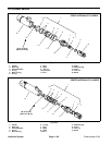
NOTE: See Lift Cylinder Service in this section for in-
formation on lift cylinder service.
Center Cylinder Installation (Fig. 63)
1. If fittings were removed from lift cylinder, lubricate
and place new O--rings onto fittings. Install fittings into
lift cylinder ports. Tighten fittings (see Hydraulic Fitting
Installation in the General Information section of this
chapter).
2. Position lift cylinder to the machine.
3. Insert pivot pin (item 8) through the frame brackets
andliftcylinder.Securepintoframewithcapscrew,
washer and lock nut.
4. Position clevis of the lift cylinder to the lift arm. Se-
cure lift cylinder clevis to the lift arm with clevis pin (item
14) and cotter pin.
5. Connect hydraulic hoses with new O--rings to the hy-
draulic fittings on the lift cylinder. Tighten hose connec-
tions (see Hydraulic Hose andTubeInstallationinthe
General Information section of this chapter).
6. Make sure that hydraulic reservoir is at correct level.
7. Start machine. Run machine at idle for several min-
utes to circulate hydraulic fluid and remove any air
trapped in the system. Stop machine and recheck hy-
draulic reservoir level.
Hydraulic
System