


Greensmaster 3150 Hydraulic SystemPage 4 -- 75
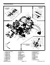
Removal (Fig. 52)
1. Before removing any parts from the hydraulic sys-
tem, park machine on a level surface, engage parking
brake, lower cutting units and stop engine.
CAUTION
Before continuing further, read and become fa -
miliar with General Precautions for Removing
and Installing Hydraulic System Components.
NOTE: The position of hydraulic fittings on the reel mo-
tor is critical to properly connect hydraulic hoses t o the
motors.
2. Label all hydraulic hose connections for assembly
purposes. Matchmark reel motor and all hydraulic fit-
tings for assembly purposes.
3. Remove hose connections from the hydraulic fittings
on the reel motor. Allow hydraulic oil to drain from hoses
into a suitable container. Put caps or plugs on ends of
hoses to prevent contamination.
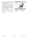
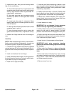
4. Loosen two (2) flange head screws that secure the
hydraulic reel motor to the cutting unit side plate (Fig.
53). Rotate motor clockwise and remove motor from cut-
ting unit.
5. Inspect r eel insert splines for wear.Replace if neces-
sary (see Reel Assembly Removal and Installation in
the Service and Repairssection of Chapter 7 -- DPACut-
ting Units).
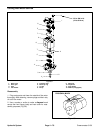
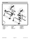
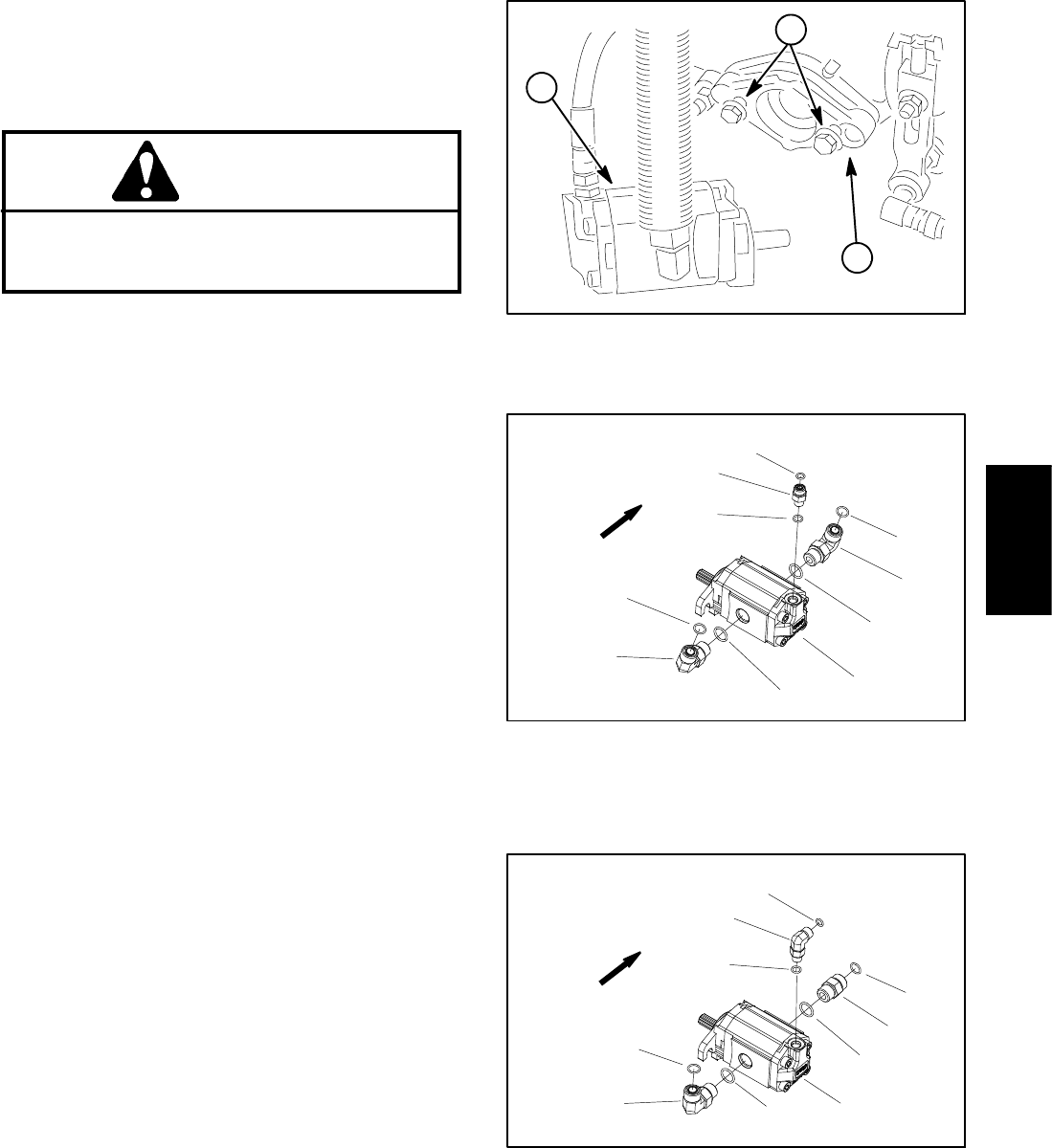
6. Remove hydraulic fittings and O--rings from the reel
motor (Figs. 54, 55 and 56). Put caps or plugs in motor
openings to prevent contamination.
Installation (Fig. 52)
1. Inspect threads and sealing sur faces of fittings and
hydraulic hoses. Replace any worn or damaged fittings.
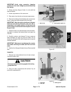
2. If fittings were removed from reel motor, lubricate
and place new O--rings onto fittings. Install fittings into
motor ports using marks made during the removal pro-
cess to properly orientate fittings (Figs. 54, 55 and 56).
Tighten fittings (see Hydraulic Fitting Installation in the
General Information section of this chapter).
3. Coat spline shaft of the reel motor with No. 2 multi-
purpose lithium base grease.
4. Install the flange head screws for the reel drive motor
into the cutting unit side plate and leave approximately
1/2 inch (13 mm) of threads exposed on e ach screw.
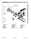
1. Cutting reel motor
2. Flange head screw
3. Cutting unit
Figure 53
1
3
2
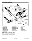
1. RH cutting reel motor
2. O--ring
3. Hydraulic fitting
4. O--ring
5. O--ring
6. Hydraulic fitting
7. O--ring
Figure 54
2
3
6
1
5
7
4
2
3
4
RH REEL MOTOR
FRONT
Figure 55
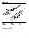
LH REEL MOTOR
2
3
6
1
5
7
4
2
8
4
1. LH cutting reel motor
2. O--ring
3. Hydraulic fitting
4. O--ring
5. O--ring
6. Hydraulic fitting
7. O--ring
8. Hydraulic fitting
FRONT
Hydraulic
System