


Greensmaster 3150 Hydraulic SystemPage 4 -- 87
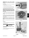
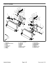
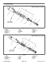
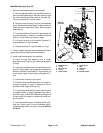
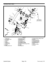
Disassembly (Figs. 64 and 65)
1. Remove the oil from the cylinder by slowly pumping
the cylinder shaft while holding the cylinder over a drain
pan. Plug both ports and clean the outside of the cylin-
der.
IMPORTANT: Prevent damage when clamping the
hydraulic cylinder into a vise; clamp on the cap end
only. Do not close vise enough to distort the barrel.
2. Mount lift cylinder in a vise. Use of a vise with soft
jaws is recommended.
3. Using a spanner wrench, rotate head clockwise until
the edge of the retaining ring appears inthe barrel open-
ing. Insert a screwdriver under the beveled edge of the
retaining ring to startthe r etaining ring through the open-
ing. Rotate the head counter--clockwise to remove re-
taining ring from barrel and head.
4. Extract shaft, head and piston by carefully twisting
and pulling on the shaft.
IMPORTANT: Do not clamp vise jaws against the
shaft surface. Protect shaft surface before mount-
ing in a vise.
5. Mountshaft securely in a vise by clamping on thecle-
vis or eye of the shaft. Remove lock nut and piston from
theshaft.Slideheadofftheshaft.
6. Remove wear ring and seal with loader from the pis-
ton. Remove O--ring, back--up ring, seal and wiper from
the head. Remove O--ring from rod.
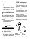
CAUTION
Use eye protection such as goggles when using
compressed air to dry cylinder parts.
7. Wash parts in clean solvent. Dry parts with com-
pressed air. Do not wipe pa rts dry with paper towels or
cloth. Lint in a hydraulic system will cause damage.
8. Carefully inspect internal surface of barrel for dam-
age (deep scratches, out--of--round, etc.). Inspect shaft,
head and piston for evidence of excessive scoring, pit-
ting or wear. Replace entire cylinder if internal compo-
nents are found to be worn or damaged.
Assembly (Figs. 64 and 65)
1. Make sure all parts are clean before reassembly.
2. Coat new seal kit components with clean hydraulic
oil.
A. Install wear ring and seal with loader on the pis-
ton.
B. InstallO--ring, back--up ring and sealon the head.
C. Install O--ring to groo ve in rod.
IMPORTANT: Do not clamp vise jaws against the
shaft surface. Protect shaft surface before mount-
inginavise.
3. Mountshaft securely in a viseby clamping on the cle-
vis or eye of the shaft. Use of a vise with soft jaws is rec-
ommended.
A. Coat shaft with clean hydraulic oil.
B. Carefully slide head onto the shaft. Install wiper
onto shaft and into head.
C. Install piston and nut onto the shaft. Torque nut
from 60 to 75 ft--lb (82 to 101 N--m).
D. Remove shaft from the vise.
IMPORTANT: Prevent damage when clamping the
hydraulic cylinder into a vise; clamp on the cap end
only. Do not close vise enough to distort the barrel.
4. Mount barrel in a vise.
5. Coat all internal parts with a light coat of clean hy-
draulic oil. Slide piston, shaft and head assembly into
the barrel being careful not to damage the seals.
6. Secure head in barrel by installing retaining ring.
Align retaining ring hole in the head with the access slot
in the barrel. Insert the retaining ring hook into the hole
and rotate head clockwise until the retaining ring is com-
pletely pulled into the barrel and the ring ends are cover-
ed.
Hydraulic
System