


Greensmaster 3150
DPA Cutting Units
Page 7 -- 20
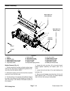
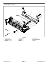
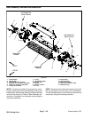
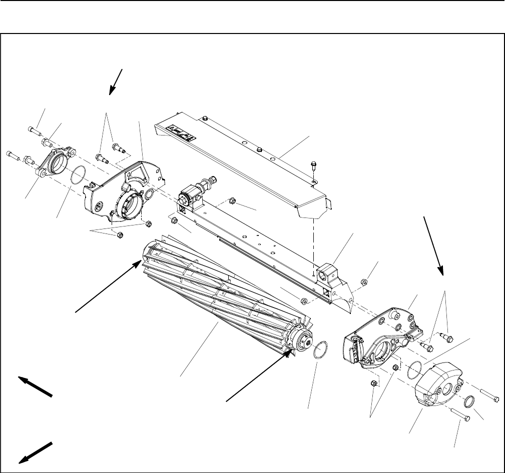
Reel Assembly Removal and Installation
1. Crossmember
2. LH side plate
3. Flange head screw (2 used)
4. Shoulder bolt (2 used per side plate)
5. Flange nut (2 used per side plate)
6. Cutting reel assembly
7. O--ring
8. Cap screw (2 used)
9. RH side plate
10. Weight
11. Hex nut (4 used)
12. O--ring
13. Grass shield
14. Flat wire spring
15. Reel motor adapter
16. Socket head screw (2 used)
17. Expansion plug
Figure 21
FRONT
RIGHT
Grease OD
210 to 240 in--lb
(24 to 27 N--m)
4
2
9
5
13
1
4
5
5
5
11
210 to 240 in--lb
(24to27N--m)
surface
Grease OD
surface
6
14
11
3
7
15
16
8
10
12
17
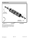
NOTE: This section provides the procedure for remov-
ing and installing the cutting reel assembly (cutting reel,
flocked seals, reel bearings, bearing lock screw and reel
nut) from the cutting unit. Refer to Reel Assembly Ser-
vice later in this section for information on servicing the
cutting reel assembly.
NOTE: Removal of the cutting reel requires removal of
the LH side plate from the cutting unit crossmember.
The RH sidep late does not have to be removedfrom the
frame when using the following procedure.