


Greensmaster 3150Hydraulic System Page 4 -- 104
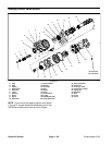
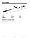
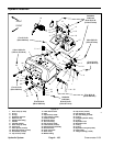
3. If removed, install solenoid valve assembly, fittings
and hoses using Figure 76 as a guide.
A. Torque fittings to values shown in Figure 76.
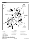
B. If solenoid valve manifold was removed from hy-
draulic reservoir, apply antiseize lubricant to threads
of cap screws (item 22). Torque screws from 30 to60
in--lb (3.4 to 6.7 N--m).
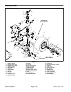
4. Position leak detector tank to hydraulic reservoir.
Connect valve hose (item 10) to solenoid valve fitting
and secure with hose clamp (item 1).
5. Connect overflow hose (item 25) and secure with
hose clamp (item 9).
6. Position carbon canister and bracket to the leak de-
tector tank.
IMPORTANT: Do not over tighten cap screws that
secure leak detector tank. Threads in hydraulic
reservoir may become damaged if screws are over
tightened.
7. Secure leak detector tank to hydraulic reservoir:
A. Apply antiseize lubricant t o threads of cap screws
(items 14 and 17) used to secure leak detector tank.
B. Install four (4) cap screws (items 14 and 17), flat
washers (item 13), neoprene washers (item 12) and
spacers (items 11 and 18).
C. Torque cap screws from 30 to 60 in-- lb (3.4 to 6.7
N--m).
8. Connectleak detectorh arness to main wire harness.
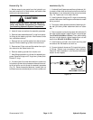
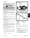
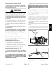
9. Connect pump inlet hose to gear pump and secure
with hose clamp (Fig. 77).
NOTE: Monitor hydraulic fluid level in sight window on
leak detector tank. As air is removed from the hydraulic
circuit, fluid level may need to be topped off after initial
fill.
10.Remove cap from hydraulic reservoir and slowly fill
to the cold fill level mark.
11.Check leak detector with ignition key switch in RUN
position. The leak detector alarm should sound when
leak detector test switchis helddown foro ne (1) second.
12.If the alarm f ails to sound, check to see if all connec-
tions are secure.
13.Verify leak detector operation.