


Greensmaster 3150
DPA Cutting Units
Page 7 -- 25
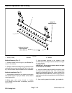
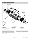
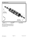
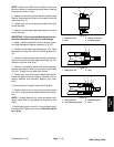
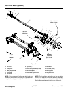
Disassembly of Cutting Reel (Fig. 23)
1. Remove reel nuts (items 5 and 6) from cutting reel.
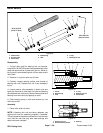
The black reel nut (item 6) has LH threads and is
installed in end of reel shaft identified with a groove that
is just inside of reel spider (Fig. 24).
2. Slide bearings from reel shaft.
3. Note orientation of flocked seals for assembly pur-
poses. Remove seals from reel shaft.
Inspection of Cutting Reel (Fig. 23)
1. Inspect reel bearings to insure that they spin freely
and have minimal axial play.
2. Inspect the reelshaft as follows. If reel damage is de-
tected, replace reel.
A. Check the reel shaft for bending and distortion by
placing the shaft ends in V--blocks.
B. Check the reel blades for bending or cracking.
C. Check the service limit of the reel diameter (see
Preparing a Reel for Grinding in this section).
D. Check threads in ends of reel shaft.
3. Check the splines in the reel nuts (items 5 and 6) for
excessive wear or distortion. Replace reel nuts if dam-
age is evident.
Assembly of Cutting Reel (Fig. 23)
1. If bearings and/or flocked seals were removed from
reel shaft, discard removed components and replace.
IMPORTANT: The flocked seal should be installed
so the flocked side of the seal is toward the bearing
location.
2. Slide flocked seals (flocked side orientated toward
bearing location) and bearings fully onto reel shaft.
Bearings and seals should bottom on reel shaft shoul-
der.
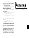
3. Install reel nuts (items 5 and 6) into reel shaft to se-
cure bearings. Black reel nut (item 6) has LH threads
and should be installed in endof reel shaft identified with
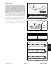
a groove that is just inside of reel spider (Fig. 24).
NOTE: Installation torque for reel nuts is from 90 to 110
ft--lb (123 to 149 N--m). It is easiest to torque these
items after the cutting reel is installed in the cutting unit
frame (see Reel Assembly Removal and Installation in
this section).
4. Thoroughly fill spline a rea of reel nuts with grease.
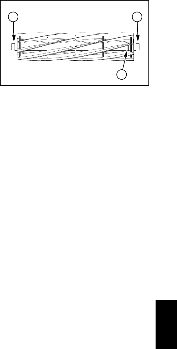
1. LH threads
2. Groove
3. RH threads
Figure 24
1
2
3
DPA Cutting
Units