


Groundsmaster 4500--D/4700--D Hydraulic SystemPage 4 -- 55
Procedure for Piston (Traction) Pump Flow
Test
This te st measures piston (traction) pump output (flow).
During this test, pump load is created at the flow meter
using the adjustable load valve on the tester.
NOTE: Before performing piston pump flow test, make
sure that traction speed is set to 100% using the In-
foCenter settings menu.
IMPORTANT: Traction circuit flow for the
Groundsmaster 4500/4700 is approximately 30 GPM
(113.5 LPM). Use 40 GPM Hydraulic Tester #AT40002
(pressure and flow) for this test (see Special Tools
in this chapter).
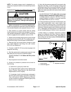
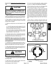
CAUTION
Prevent personal injury and/or damage to equip-
ment. Read all WARNINGS, CAUTIONS and Pre-
cautions for Hydraulic Testing at the beginning
of this section.
1. Park machine on a level surface with the cutting
decks lowered and off. Make sure hydraulic oil is at nor-
mal operating temperature, engine is off and the parking
brake is applied.
CAUTION
All wheels will be off the ground androtating dur-
ing this test. Make sure machine is supported so
it willnot move and accidentally fallto prevent in -
juring anyone near the machine.
2. Raise and support machine so all wheels are off the
ground (see Jacking Instructions in Chapter 1 -- Safety).
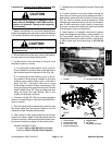
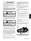
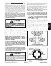
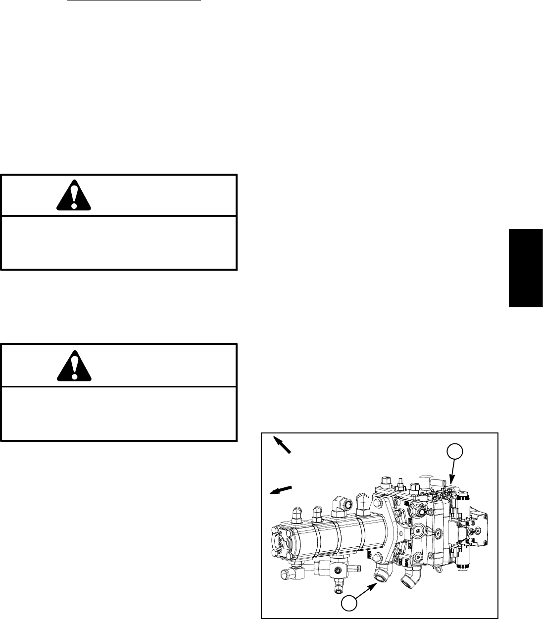
3. Thoroughly clean junction of hydraulic hose and
right side fitting on bottom of piston pump (forward port)
(Fig. 45). Disconnect hose from right side pump fitting.
4. Install tester with pressure gauge and flow meter in
series between piston pump fitting and disconnected
hosetoallowflowfromtractionpumptotester.Usehy-
draulic hose kit(see Special Tools inthis chapter) to con-
nect tester to machine. Make sure that fitting and hose
connections are properly tightened. Also, make sure the
flow control valve on tester is fully open.
5. Start engine and increase engine speed to high idle
speed.
6. Slowly push traction pedal to fully forward position.
Keep pedal fully depressed in the fully forward position.
7. Have second person watch pressure gauge on test-
er carefully while slowly closing the flow control valve
until 1000 PSI (69 bar) is obtained. Verify with the In-
foCenter display that the engine speed is still at the cor-
rect high idle speed.
NOTE: If engine speed drops during testing, pump flow
will decrease and flow test results will be inaccurate.
8. Observe flow gauge. Flow indication should be
approximately 30 GPM (113 LPM).
9. Release traction pedal to the neutral position, open
flow control valve on tester and shut off engine. Record
test results.
10.If flow is less than 24 GPM (91 LPM), consider the
following:
A. The traction pedal is not calibrated correctly (see
Traction Pedal Calibration in the Adjustments sec-
tion of Chapter 5 -- Electrical System).
B. The piston pump swash plate is not being rotated
fully (e.g. traction speed is not set to 100%).
C. The forward traction relief valve is leaking or
faulty.
D.Thepistonpumpneedstoberepairedorre-
placed as necessary.
11.Make necessary repairs before performing any addi-
tional traction circuit tests.
12.When testing is complete, disconnect tester from
pump fitting and machine hydraulic hose. Reconnect
hose to pump fitting. Lower machine to ground.
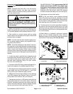
1. Piston (traction) pump 2. Forward port fitting
Figure 45
FRONT
RIGHT
1
2
Hydraulic
System