


Groundsmaster 4500--D/4700--D Hydraulic SystemPage 4 -- 83
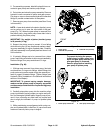
IMPORTANT: Use caution when clamping gear
pump in a vise to avoid distorting any pump compo-
nents.
3. Securethefrontcoverofthepumpinavisewiththe
drive shaft pointing down.
4. Loosen the four (4) cap screws that secure pump as-
sembly.
5. Remove pump from vise and remove fasteners.
6. Support the pumpassembly and gently tap the pump
case with a soft face hammer to loosen the pump sec-
tions. Be careful to not drop parts or disengage gear
mesh.
IMPORTANT: Mark the relative positions of the gear
teeth and the thrust plates so they can be reassem-
bled in the same position. Donot touch the gear sur-
faces as residue on hands may be corrosive to gear
finish.
7. Remove the thrust plates and seals from each pump
section. Before removing each gear set, apply marking
dye to mating teeth to retain ”timing”. Pump efficiency
may be affected if the teeth are not installed in the same
position during assembly. Keep the parts for each pump
section together; do not mix parts between sections.
8. Clean all parts. Check all components for burrs,
scoring, nicks and other damage.
9. Replace the entire pump assembly if parts are ex-
cessively worn or scored.
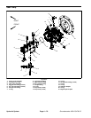
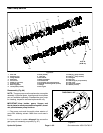
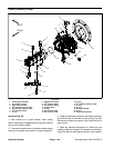
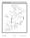
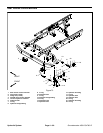
Assembly (Fig. 66)
1. Apply clean hydraulic oil to all pump parts before as-
sembling.
NOTE: Pressure seals and back--up gaskets fit in
grooves machined into thrust plates. Body seals fit in
grooves machined in body faces.
2. Assemble pump sections starting at front cover end.
Apply grease or petroleum jelly to new section seals to
hold them in position during gear pump assembly.
3. After pump has been assembled, tighten cap screws
and nuts by hand. Rotate the drive shaft to check for
binding. Protect the shaft if using a pliers.
4. Tighten the four (4) cap screws evenly in a crossing
patterntoatorqueof33 ft--lb (45 N--m).
Hydraulic
System