


Groundsmaster 4500--D/4700--DCutting Decks Page 8 -- 16
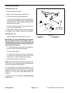
Front Roller Service
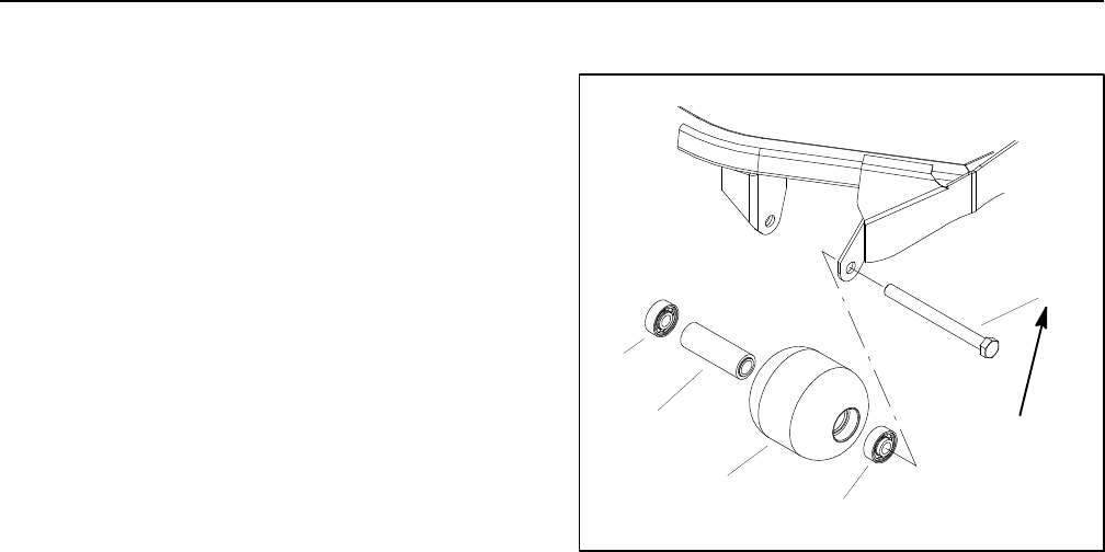
Disassembly (Fig. 18)
1. Remove roller mounting bolt.
2. Remove roller assembly from carrier frame.
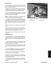
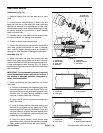
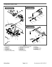
3. To remove bearings and bearing spacer:
A. Insert punch through end of roller and drive oppo-
site bearing out byalternating tapsto oppositeside of
inner bearing race. There should be alip ofinner race
exposed for this process.
B. Remove bearing spacer. Remove second bear-
ing from roller using a press.
4. Inspect roller housing, bearings and bearing spacer
for damage o r wear. Replace components as needed.
Assembly (Fig. 18)
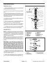
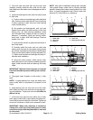
1. Install bearings and bearing spacer into roller:
IMPORTANT: Use Front Roller Bearing Installation
Tool (see Special Tools in this chapter) when in-
stalling bearings into roller. This tool ensures that
no sideload is appliedto thebearings during install-
ation into the front rollers.
A. Press first bearing into housing. Press equally on
inner and outer races during installation.
B. Insert be aring spacer.
C. Press second bearing into roller housing press-
ing equally on inner and outer races until the inner
race comes in contact with the bearing spacer.
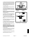
2. Install roller assembly to deck frame.
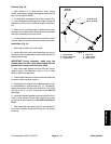
NOTE: Securing roller assembly with a gap larger than
0.060 inch (1.5 mm) creates a side load on bearings and
can lead to premature bearing failure.
3. Verify that there is no more than a 0.060 inch (1.5
mm) gap between roller assembly and the roller mount
brackets of the deck frame. If this gap is larger than
0.060 inch (1.5 mm), shim excess clearance with 5/8”
washers.
4. Insert mounting bolt and tighten to 65 to 95 ft--lb (89
to 128 N--m).
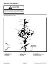
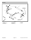
1. Mounting bolt
2. Bearing
3. Bearing spacer
4. Front roller
Figure 18
65 to 95 ft--lb
(89 to 128 N--m)
3
4
2
1
2