


Groundsmaster 4500--D/4700--D Page 7 -- 17 Chassis
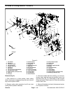
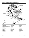
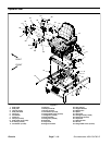
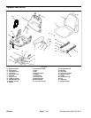
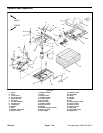
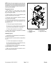
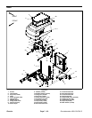
Removal (Fig. 17)
1. Park machine on a level surface, lower cutting
decks, stop engine, apply park ing brake and remove
key from the ignition switch.
2. Disconnect seat electrical connector from machine
wire harness.
3. Support console arm assembly to prevent it from
shifting.
4. Remove flange nut (item 29) and carriage screw
(item 28) that secure support bracket (item 24) to sup-
port channel (item 22).
5. Remove cap screw (item 30) that secures console
arm support (item 23) to coupling nut (item 32).
6. Remove cap screw (item 27), flat washer (item 11),
spacer (item 26) and seat belt buckle (item 31) from seat
and console arm support (item 23).
IMPORTANT: Make sure to not damage the electri-
cal harness or other parts while moving the console
arm assembly.
7. Carefully move console arm assembly away from
seat.
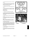
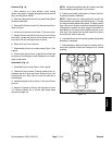
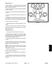
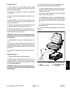
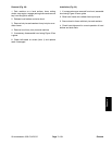
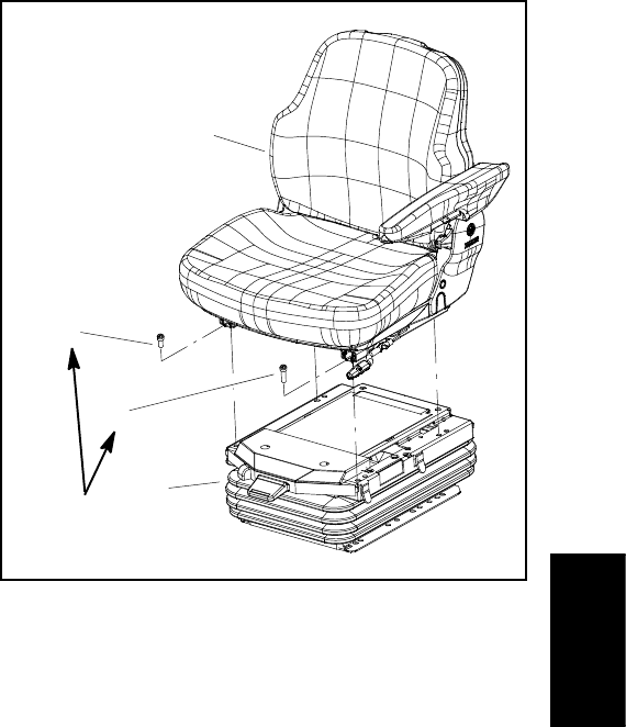
8. Remove four (4) torx head screws that secure seat
to seat suspension (Fig. 18). Note that the screw near
the seat adjustment handle islonger thanthe otherthree
(3) screws.
9. Lift seat from seat suspension and remove from ma-
chine.
Installation (Fig. 17)
1. Carefully position seat to seat suspension.
2. Secure seat to seat suspension with four (4) torx
head screws (Fig. 18). Make sure that longer screw is
positioned near the seat adjustment handle. Torque
screws 18 ft-- lb (25 N--m).
IMPORTANT: Make sure to not damage the electri-
cal harness or other parts while moving the console
arm assembly.
3. Position an d secure console arm assembly to se at.
Install all fasteners before fully tightening them.
A. Secure support bracket (item 24) and support
channel (item 22) with flange nut (item 29) and car-
riage screw (item 28).
B. Secure console arm support (item 23) to coupling
nut with cap screw (item 30).
C. Place flat washer (item 11), seat belt b uckle (item
31) and spacer (item 26) between seat and console
arm support (item 23). Secure with cap screw (item
27).
D. Fully tighten all fasteners to secure console arm
assembly to seat.
4. Connect seat electrical connector to m achine wire
harness.
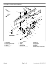
1. Seat
2. Suspension assembly
3. Screw (M8x12) (3 used)
4. Screw (M8x16)
Figure 18
2
3
1
4
18 ft--lb
(25 N--m)
Chassis